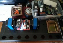
If you want to replicate a circuit of the past instead, my preference goes to the amplifier designed by Grundig for the 1958/1959 top of the range consoles, and later sold globally as standalone part with the designation NF2. My specimen had been overhauled/recapped in the early '70 and again mid-'90 before this year restoration, so I am not the only one that likes the way it sounds I guess. I replaced the 100uF filter capacitors with 270uF and the selenium rectifiers with silicon ones plus a dropping resistor. Power and output transformers are built according to the commercial quality of the time, they would be classified as entry level by today standards.
Attachments
I hooked EL84 UL grids together & tied to B+ thru 1k resistors for each channel in ST-35 design. Ran like this w/ no problem. ST-35 uses ECC832 instead of ECC83, though.
Getting polarity correct on global feedback loop is a good first challenge, imo. As long as the beginner is warned first sound test may be noisy... & what to do to correct it.
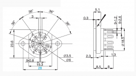
Make sure chassis holes will fit available tube socket dimensions, pic'ed below typical 9 pin noval.
Jim
Getting polarity correct on global feedback loop is a good first challenge, imo. As long as the beginner is warned first sound test may be noisy... & what to do to correct it.
Make sure chassis holes will fit available tube socket dimensions, pic'ed below typical 9 pin noval.
Jim
Attachments
The Grundig amplifier does have a nice vintage sound, midrange and voices are warm and center stage. I am now using it paired with small Warfedale D310 bookshelf speakers (nominal impedence is 4 ohms). It was nothing special back then, a premium-range mass produced amplifier, but the serviceability and overall build quality are a step or two above today devices on the same market segment.
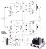
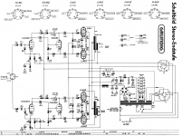
I attach to this post the schematic from the Grundig SO181 Konzertschrank service manual, it does lists all the relevant voltages and currents.
On later models, Grundig changed coupling capacitor values to 33nF or 47nF. I installed 47nF for the EL84 and 22nF (original value) for the preamp section. The global feedback is pretty high. As TG said, this means that there is oscillation and motoboating risk if the build is done improperly. On later NF2 models (1960-65), Grundig added a small inductor on the feedback loop, but on the 1958-59 model the schematic is the one on this post. Due to the high NFB, increasing the values of the cathode capacitors will result in instabilities. According to my tests, the original values of 22uF and 47uF give the best results. For the preamp section I installed organic polymer types, they have a quite low ESR. I increased the main filter capacitor to 270uF 450V (instead of the original 100+100uF) and added a 330K 1W bleeding resistor in parallel; C19 and C20 also are 270uF now while C21 is 220uF. The bias supply diode is now UF4001 with a 47 ohm series resistor; the high voltage bridge rectifier is in series with a 100 ohm 25W resistor. The value of C22 should NOT be increased. The amplifier does use a mixed automatic/fixed bias. I briefly fitted unmatched output tubes and the amplifier copes pretty well to the anomaly, but the bias is not adjustable so changing tube brand will change the operating point slightly. I fitted NOS Philips tubes, they give the exact values on Grundig schematic. I added a 10 ohm sourge suppression thermistor in series to the mains supply; this will balance the increased filter capacitors and also enables the use of a 1A mains fuse instead of 1.25A. I added a 220nF x2 capacitor in parallel to the primary winding of the power transformer to suppress the power off noise. R1 and R2 are now 39k (any lower will result in motorboating at low volume), the volume potentiometer I added is Alps RK27 100K. R15 and R16 trimmers are there to balance the phase inverter. I have replaced them and the series resistor with 47K 1W fixed resistors. This change has also been done by Grundig on amplifiers manufactured from 1960 onwards.
Attachments
I think to go with the Grundig schematic, because the output transformers I have, are not ultralinear.
What TG said. And EL84BH does very well in pentode (no UL) or triode modes.
The Grundig circuit looks like a fine amp too. Output transformer details? Primary probably 8k? Could stability be a problem with non-Grundig transformers?
Last edited:
I believe that the Grundig 9078-046 transformer primary is 8K but I haven't measured it. The 1960 version of this amplifier does have a different output transformer part number with the same size and connections. They also added a small inductor in series with the RC feedback coupling and rearranged the resistors at the input of the first triode. I guess they realized that phase margin was too thin with those transformers, but they wanted to keep the same feedback. My wild guess is that stability will improve with a better quality transformer such as the one I see on post #2. If the 5 ohm tap is not available, feedback resistor value should be changed anyway, so it could be tuned to the available transformer.
NF2 price has hit insane levels lately for that type of amp. It is definitely worth building a replica with good parts rather than buy a unrestored original at the asking price of auction sites. I was lucky enough to find mine inside a dilapidated console in a thrift store. I've been thinking about building a replica for some time to hear why it's so sought after.
- Home
- Amplifiers
- Tubes / Valves
- EL 84 PP schematic