Well I suppose the word is damn damn and damn(yep thats three
After looking for a pair of ESL57s I just dont think they will work in my hi fi room.
ESL57s about three foot wide.Total width of room is 9ft 9 inches and length 11ft 8inches.Thinkng in all honesty thats pushing it for any electrostatic.
After looking for a pair of ESL57s I just dont think they will work in my hi fi room.
ESL57s about three foot wide.Total width of room is 9ft 9 inches and length 11ft 8inches.Thinkng in all honesty thats pushing it for any electrostatic.
No you don't. This is urban myth. They are perfectly stable without reproducing the shunt capacitance of the original C2/3, which any case was only 30pF, not 1nF. The KT66s already have that much in Cgk, you don't need to add to it.
I don’t think this one is a myth. Quad’s servicing datasheet mentions when replacing metal cased PIO caps with film types, to then add 33pF between pins 2 and 6 of each EF86 valve base. They used to recommend 350V silver mica. Also interesting to note that in their new reproduction Quad II monoblocks, these caps are also incorporated, albeit with what appear to be ceramic disc capacitors this time, and on the KT66 bases & ground.
Last edited:
These are standard electrolytic caps placed into the can, they are not oil filled types.Leave the oil-filled capacitors C4/6 alone unless one of them is s/c, which happens occasionally.
I'm aware that Quad do it but IMHO they are mistaken. For a start consider that a Kt66 already has Cag of about 30pF, so there is no need for the extra leakage capacitance at al, so the assertion that the leakage was designed into the circuit lacks motivation. Secondly, ask yourself why a signal out of V1 that has already had an LP pole imposed by 33pF from plate to grid should have another such pole imposed by the same in V2. This can only mean that the signal into V4 gets two such poles. It's pointless from both points of view. Thirdly, consider that Quad GmbH don't fit them. In over sixteen years of not fitting these capacitors I have never seen a Quad II oscillate.I don’t think this one is a myth. Quad’s servicing datasheet mentions when replacing metal cased PIO caps with film types, to then add 33pF between pins 2 and 6 of each EF86 valve base. They used to recommend 350V silver mica. Also interesting to note that in their new reproduction Quad II monoblocks, these caps are also incorporated, albeit with what appear to be ceramic disc capacitors this time, and on the KT66 bases & ground.

Hi All
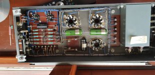
Haven't fitted R12 yet nor R1.C1 has been changed and yes Coupling caps are Russian K75s (R1 and R12 in fact in picture on left of quad but hardly a sharp focus pic)C4 and C6 seem to measure ok but will probably change them.
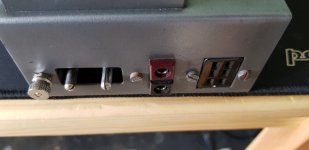
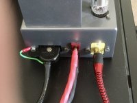
Will split mains before it goes into quad and put a ring socket on earth then mount on grounding post post
Have checked grounding post has continuity with the chassis
Cheers all
Haven't fitted R12 yet nor R1.C1 has been changed and yes Coupling caps are Russian K75s (R1 and R12 in fact in picture on left of quad but hardly a sharp focus pic)C4 and C6 seem to measure ok but will probably change them.
Will split mains before it goes into quad and put a ring socket on earth then mount on grounding post post
Have checked grounding post has continuity with the chassis
Cheers all
Attachments
It doesn't look like that to me. C1 might have been changed in about 1984 but it looks ancient now. And no reason not to use another Russian KY for C1.It looks like C1 and the coupling caps have been changed.
Well spotted that eagle eyed man.Mundorf as only got 4 russian ones and had the mundorfs laying about.C-1 looks like a Mundorf m-cap with some of the lettering scraped off... I don't think Mundorf was around in 1984. 🙃
- Home
- Amplifiers
- Tubes / Valves
- Quad II parts advice please.