Thanks, I wasn't aware of that and I was only basing the choice on datasheet. Thanks for the info!Unknown until about 10 years ago, mosfets also have a secondary breakdown limit that is not well defined, or even stated in some data sheets. Most mosfets available today are designed for switch mode operation. Long term operation in the linear region can result in random failures. ON Semi / Fairchild does not show this at all in their SOA graphs in the data sheet.
So you stay safely below 200V across it. Well noted. Have you also tested bigger brothers of it? In this case I would need somenthing like a PQPFxP50 to withstand the 400V swing of the preamp.I have not yet blown a Fairchild FQPF9P25 mosfet, but I keep them under 10 watts and 75 degrees C. The chassis plate itself will not be a sufficient heat sink for two mosfets each dissipating 35 watts.
Thanks again to save me from fireworks and injuries.If you experiment with this operation put a fast blow fuse of 1/2 to 1 amp in the cathode lead of the tube. It may save the tube and OPT. Do not try to fuse the plate with a 250 volt AC fuse, it may explode on DC.
Very interesting! May I ask you to share the LTSpice file you used? I would like to perform some tests and compare results.The surprise to me was that the screen voltage modulation in CED with a ground-referenced screen supply seems to make this even more pronounced and increase gain. I think the screen voltage modulation is responsible for more of the improvement to the curves than the series feedback is, but there does appear to be an improvement for that as well.
Thanks!
Basically what you have there is a source follower where the drain is grounded and the source copies the signal at the gate. In this configuration a pmosfet does a source follower, whilst a nmosfet would contribute with its gm, that is what we don't want.
OK, that makes perfect sense.
In the schematic with two 100k R-fbk and two 68k to ground, B+ is not listed. Given how high the grid is I am going to assume it is fairly high( as the tube will still need a respectable B+ anode-cathode, yes?).
Also given the 68k:100k we have something excess to the usual suggested by Schade of 10% fbk, right?
I'd be quite tempted to try this leaving the input stage un-Schaded at first. Likely a try with a slightly larger pentode( EL84-6AV5 window, 6V6 maybe? ). Un-Schading the input would also probably let me get away with a resistive plate load too...
")
cheers,
Douglas
You can see the Va label, that is 500V, scale it down with the voltage divider and you'll find it will be around 202V whilst the cathode is above that (as it has to be).
The feedback here is 40%, even if based on George's feedback it could be too much stress for the pMosfet, and could be better to reduce it.
How do you want to connect the grid then?
The feedback here is 40%, even if based on George's feedback it could be too much stress for the pMosfet, and could be better to reduce it.
How do you want to connect the grid then?
Ultimately it could be that I will take a very mild Schade applied to a medium sized transmitting triode I want to use. Its plate resistance is at high end of marginal, and the MOSFET source follower at the 100mA of idle would likely do it. From zero bias on the triode I need about +/- 35V of swing...and the FET drivers put an end to the hunt for a matching3k:600 line OPT. Back to two stages... and pentode voltage amplifiers.
So given the partial thoughts I am assembling in the aether, 5% Schading( 100k dropping from anode to grid, and 5k grid to ground with a 600V B+ leaves the grid at ~28V...and so I'll need a bit of MOSFET headroom. Is there any issue tying the drain to a solid -20V rail?
cheers,
Douglas
and pentode voltage amplifiers.So given the partial thoughts I am assembling in the aether, 5% Schading( 100k dropping from anode to grid, and 5k grid to ground with a 600V B+ leaves the grid at ~28V...and so I'll need a bit of MOSFET headroom. Is there any issue tying the drain to a solid -20V rail?
cheers,
Douglas
Last edited:
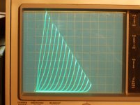
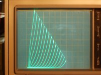
I did some curve tracing for a 31LZ6 Sweep tube using UnSET. Both pics are 50 mA/div Vert, 50V/div Horiz. and 100V supply for grid 2. 31LZ6 doesn't have as sharp of pentode knees as the 6HJ5, not sure that makes any difference here.
1st pic has the Vg2 supply grounded, so Vg2 to K is varying with Cathode drive V. Using 4V steps.
2nd pic has the Vg2 supply floated on the cathode, so Vg2 to K is constant, using 5V steps here. (no assisting Vg2 drive this way)
I was going to do a normal shunt "Schade" curve trace too, but the tracer crapped out. When I get it fixed I'll do that. I also wanted to do an internal triode trace for the 31LZ6, but that will have to wait too. Previous 31LZ6 triode tracing looked typical for a Sweep tube in triode mode, with some Mu variation (roll-over in curves)
I see the same variation in the bottom of the Unset curves bends at low current here as in the simulations by Spreadpectrum. Looks like one wants to keep Vg2 to K more close to constant for better triode emulation.
There could be some advantage in having some Vg2 drive though, since it seems to remove the roll-over effect, but fully grounded Vg2 may be putting too much correction in, causing the curve bending at the low current ends to actually tighten up a little at the HV side.
Attachments
Last edited:
Very interesting! May I ask you to share the LTSpice file you used? I would like to perform some tests and compare results.
Thanks!
See attached. Don't laugh at my ugly hacking of your schematic! I was trying to be quick.
I thought it was very interesting how the normal CED curves without the floating supply had less rollover at high voltages than at lower voltages.
Attachments
Might be interesting to use external grid 2 drive exclusively, with series grid 1 Fdbk. Darn curve tracer had to crap out just when it was getting interesting.
Then make a P-P with the new type of roll-over on one side and the old type on the other side, using the internal triode for that. Definitely a new type of SE like sound. Rock n' Rollover.
Then make a P-P with the new type of roll-over on one side and the old type on the other side, using the internal triode for that. Definitely a new type of SE like sound. Rock n' Rollover.
Last edited:
A note on my feedback divider choices:
I wanted to compare the series vs parallel feedback separate from the screen voltage modulation effect so I adjusted the parallel feedback resistor divider until the gains were equal between the CED with constant Vg2-k and the parallel feedback case.
Then I changed to a ground referenced supply for the screen in the CED configuration to examine the screen voltage modulation effect separately.
Also, I used the somewhat heavy feedback in zintolo's original schematic in this thread. One could try various percentages and see how that affects things.
So you are hyper-triodizing a triode? Just ground the pMosfet and guive its gate a bias higher than +28V (how much depends on the triode you are using as a power tube). Just note that you'll need to drive that stage with 70Vpp plus 4.8% of the total swing of the anode of the triode. If you supply it at 600V and it swings EG 1kV you'll need around 120Vpp to drive it to g1=0.Ultimately it could be that I will take a very mild Schade applied to a medium sized transmitting triode I want to use.
[omissis]
From zero bias on the triode I need about +/- 35V of swing...
[omissis]
...leaves the grid at ~28V...and so I'll need a bit of MOSFET headroom.
This brings back from chthonian abyss of my memory Wavebourn suggesting to have a very low AC impedance between g2 and k, and the importance to have them follow each other. I don't remember if it was here talking about GU50 or on his (unfortunately now dead) forum.Looks like one wants to keep Vg2 to K more close to constant for better triode emulation.
Thanks for sharing and for the hack! I'm intrigued by these new considerations on further possible improvements and possible developements.I thought it was very interesting how the normal CED curves without the floating supply had less rollover at high voltages than at lower voltages.
In parallel I will do some simulations driving g2 through a common-collector BJT with the base driven by pentode's cathode, g1 still driven through the voltage divider and the pentode driven through the pMosfet on its cathode. Everything fixed, just changing what signal is imposed to g2.Might be interesting to use external grid 2 drive exclusively, with series grid 1 Fdbk.
😍Then make a P-P with the new type of roll-over on one side and the old type on the other side, using the internal triode for that. Definitely a new type of SE like sound. Rock n' Rollover.
Reading George's previous fireworks experience (thanks for sharing and saving me from possible injuries!) it is probably too much feedback for nowadays available components, and it would be needed to drop it to around 10%. It's a pity, because I liked the balance I got from the available clean swing of the driver and the performance of the KT88 with this amount of feedback.I used the somewhat heavy feedback in zintolo's original schematic in this thread. One could try various percentages and see how that affects things.
So you are hyper-triodizing a triode? Just ground the pMosfet and guive its gate a bias higher than +28V (how much depends on the triode you are using as a power tube). Just note that you'll need to drive that stage with 70Vpp plus 4.8% of the total swing of the anode of the triode. If you supply it at 600V and it swings EG 1kV you'll need around 120Vpp to drive it to g1=0.
This pup will start at grid=0V. Class A, PP HY51A from about a 600V/100 mA idle point. 10k a-a OPT. :It was going to be cathode driven anyway, grid grounded, and bias adjusted with a variac on the plate Iron's primary.
It occurs to me that the grid current is not going to like the FBK resistors.
cheers,
Douglas
It occurs to me that the grid current is not going to like the FBK resistors.
You'd probably have to buffer it with a mosfet which if I remember correctly you are trying to avoid.
I've had good luck doing it, though. My 826 SE amp with a mosfet grid driver makes 19 watts but distortion is at .063% at 10W. The step in load doesn't seem to be much of a problem for the mosfet in my experience.
- Home
- Amplifiers
- Tubes / Valves
- Single Ended: the pentode retaliation