I believe there is a resistor from the grid to ground.
At the time, we were talking about fundamental issues of feedback, using an anode follower as the model. But things are very fluid here, and sometimes ya can't tell the players without a scorecard.
Overall, seems like a very elegant way to balance out some of the second-order non-linearities using an impedance-scaled and "positron operating" device, that also, fortuitously, lets you operate sweep valves in a much, much more efficient zone than the conventional triode connection allows. Win - win.
My only beef is with details about feedback, but I'm whiny that way, and can't help it.
All good fortune,
Chris
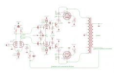
You don't have to use a separate grid bias resistor to make it work if you use a p-channel follower to drive the feedback network. See attached for an example in an amp I built several years ago.
I believe smoking-amp is saying that even if you do it the way I did it, it is fundamentally inferior to series feedback for the same amount of feedback.
I believe smoking-amp is saying that even if you do it the way I did it, it is fundamentally inferior to series feedback for the same amount of feedback.
Attachments
I believe smoking-amp is saying that even if you do it the way I did it, it is fundamentally inferior to series feedback for the same amount of feedback.
Shunt feedback does apply an extra burden to the driving stage, and most folks just ignore it. The working impedance at the summing node is Rfb / A+1. Not a surprise issue if you're already driving G2, etc. but important in the Baby Huey, RH84, Stephe's new miniature, etc. world.
All good fortune,
Chris
Thank you for your intervention 6A3sUMMER, yes you are correct, but KT88 is just an example and this kind of schematic can be applied to tetrodes, pentodes, etc...Nomenclature is important
The Key word is Beam, not pentode.
Just saying.
That's the reason why I wrote generically "pentodes" as opposite to "triodes" and so their retaliation.
I think you replied to my question to Tubelab_com on the reasons why he suggests 10% a-g1, because he has found that this generally gives a more euphonic harmonic slope?One can leave some natural "roll-over" effect in the curves by using a higher Mu factor in the UnSET R divider I believe.
So, basically, I see the Mu variation along a load line is opposite for "shunt" Schade versus normal triodes or UnSET. Although Unset can be adjusted for almost no Mu variation using a low Mu factor R divider.
You can try this way: Transistor Curve Trace in LTSpice - YouTubeThis would probably be a great job for a simulator. Maybe this will be what drives me to build some circuits in LTSpice. I have no idea how to get it to draw curves but I've seen it done so there must be a way.
The 10% number is a general starting point that I arrived at by curve tracing the CED (the tube / mosfet pair) made with several different TV sweep (line output) tubes and a few different mosfets.
Changing the ratio affects the "Mu" of the resulting "triode" but also affects the idle voltage across the mosfet. Increasing the feedback lowers the Mu but puts more voltage across the fet unless a more complex power supply is used. Lowering the Mu increases the drive voltage requirement as well. There is a point where too much feedback will require a bigger heat sink on the fet than can be used in a PC board built amp, and require more drive than a typical two stage amp can make.
We have seen several ways to get tons of clean gain from a single pentode, but depending on the tube microphonics will become an issue at high gains. Every tube is different in this regard, but most will get worse over time, especially if subject to vibration as in a guitar amp. I think I'm on my 4th or 5th input tube in my high gain guitar amp and I don't use it that much any more.
10% is a good compromise for the average mid size TV sweep tube. Most of my testing has been done with sweep tubes, where 10% seems to work fine. A KT88 or 6L6GC might do better with something else, but I have not done a whole lot of testing with them yet.
Thank you very much.
Here I put the concept to the extremes with 40% plus 40%UL just because I wanted to push (on LTSpice only by now) the power (the higher the nfb the higher the available power) and the DF with that high-gain and low-THD driver (it can swing very clean 400 Vpp on sims).
As for the dissipated power (there are around 35Wpc on the pmosfets in this scheme) I'm thinking to use a heatsing as top of the amp (wook on sides), lasercut, and fix the pmosfet to it in order to better dissipate the power. For powertubes I'd cut only the diameter of the socket and then mill a bigger diameter for the tube glass.
I have some 6E5P coming to perform some tests on them as well.
As I'm moving into a new house, all tests will probably be postponed by some months, but then I'll have more space to experiment.
Thank you very much.
Here I put the concept to the extremes with 40% plus 40%UL just because I wanted to push (on LTSpice only by now) the power (the higher the nfb the higher the available power) .....As for the dissipated power (there are around 35Wpc on the pmosfets in this scheme)
The available power output also goes up with increased feedback because you are shifting more of the total work to the mosfet. Your total dissipation limit increases as long as you stay within the limits of the mosfet.....
Unknown until about 10 years ago, mosfets also have a secondary breakdown limit that is not well defined, or even stated in some data sheets. Most mosfets available today are designed for switch mode operation. Long term operation in the linear region can result in random failures. ON Semi / Fairchild does not show this at all in their SOA graphs in the data sheet.
I have had small mosfets short which leaves the tube with a grounded cathode and a positive voltage on the grid. It will not live long, and in a high powered amp can even explode!
I have not yet blown a Fairchild FQPF9P25 mosfet, but I keep them under 10 watts and 75 degrees C. The chassis plate itself will not be a sufficient heat sink for two mosfets each dissipating 35 watts. If you experiment with this operation put a fast blow fuse of 1/2 to 1 amp in the cathode lead of the tube. It may save the tube and OPT. Do not try to fuse the plate with a 250 volt AC fuse, it may explode on DC.
... put a fast blow fuse of 1/2 to 1 amp in the cathode...
Does anyone make/sell circuit breakers in this range? I found some cheap 1A surplus fast breakers years ago, but I don't seem to see any now. Very handy for experimenting.
In my case I had a tube arc due to faulty arithmetic. A 6HJ5 will not live at 350 watts of dissipation even for a nanosecond. A 36LW6 however lived at 600+ watts for long enough for me to manually trace its curves into the Chernobyl zone.
The power supply I have is an old 60Hz "switcher," basically a triac style light dimmer feeding a big iron transformer / bridge / CLC filter controlled by a very slow feedback loop with about a 1 second reaction time. The output filter has a combined 1000 uF of capacitance and it goes to 650 volts. When "stuff" happens, tubes and plastic semiconductors explode, PCB traces and small parts vanish, and one of my OPT's became a magnet.
I would venture to guess that a mechanical circuit breaker would not fare well, but I have never tried it. I'm also guessing that a full on tube arc would destroy a fuse, but a minor meltdown would blow the fuse causing the cathode voltage to rise, cutting off the tube.....provided that it's not gassy.
Attachments

My only experience with the Airpax magnetic breakers is that Ten Tec sold them for protection of the finals in their radios, if they were being used mobile, as there was no internal vswr fold back protection.
Best I recall, they specified that only the Airpax was satisfactory, and I never popped a final - they were pretty fast to trip. Now that I think of it, they were about $20 ish back then, IIRC.
Best I recall, they specified that only the Airpax was satisfactory, and I never popped a final - they were pretty fast to trip. Now that I think of it, they were about $20 ish back then, IIRC.
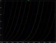
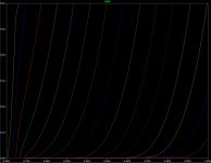
Here are the curves from LTSpice. First is Shunt feedback, second is CED with Vg2-k held constant, and last is normal CED curves.
Series feedback seems to be slightly lower rp and a little less rounding at low currents/high voltages than shunt feedback.
The surprise to me was that the screen voltage modulation in CED with a ground-referenced screen supply seems to make this even more pronounced and increase gain. I think the screen voltage modulation is responsible for more of the improvement to the curves than the series feedback is, but there does appear to be an improvement for that as well.
Attachments

- Home
- Amplifiers
- Tubes / Valves
- Single Ended: the pentode retaliation