Just so you're aware of the origin of this thread . . . The Loesch article, and the section on power supplies specifically, was introduced and discussed in the other thread, starting on page 55: DHT driver for triode wired SE EL84, 6V6 or EL34
Here's the passage that has me so confused:
"The Impedance of the Powersupply must be small in comparison to the Anode (Plate) Impedance of the Valve the PSU feeds at all frequencies at which the Amplifier is being operated. The load-impedance does not factor at all here. I suggest a ABSOLUTE MINIMUM RATIO of 1:10 between Anode Impedance and PSU Impedance for the whole Frequency Range required for the Amplifier. For a 300B the Anode Impedance is around 700 Ohm. For a lowest Frequency of 4Hz (my definition of audibility of Audio Frequencies is 4Hz-100kHz @ -3db or 20Hz - 20kHz @ -0.1db) our PSU-Impedance should be hence less or equal to 70 Ohm (700 Ohm / 10). The rest is simple math. It leaves us with the result that the final filter capacitor for a conventional PSU arrangement, should be at least 560uF when used with a single 300B."
Tizman then posted a calculator (although not the same one I posted) and observed that if you enter the parameters set forth by Loesch (70 ohms and a -3db point of 4Hz) the high pass calculator came up with the same cap value (560uf) which he suggests is optimal.
Loesch never uses the term "high pass" and he doesn't reference any calculator, he just says "The rest is simple math". The fact that the high pass calculator comes up with the same results as Loesch led some people to state that the PS forms a high pass filter. But does it?
The high pass I'm most familiar with in an amp is the one formed by the coupling cap and the grid leak resistor that follows it. My confusion stems from two things.
First, my inability to recognize the same configuration of parts in the PS that I see when I look at the coupling cap / grid leak. Maybe it's there (in the PS node that supplies the input tubes) and I'm just blind and not recognizing it. But I'm pretty sure I'm not deaf.
The second source of my confusion is that when I input a 50hz signal into my breadboarded amp, and compared a 50uf cap and a 0.01uf cap in the node that supplies the input tube, I heard no rolloff.
According to the high pass calculator, a combination of a 3.9k R and a 0.01uf cap should have a rolloff at 4kHz. Yet the 50hz signal was just as loud with a 0.01uf cap as it was with a 50uf cap, which would put the rolloff at 0.82Hz. Based on this experiment, my conclusion is that the PS does not form a high pass filter.
If I'm wrong, why am I not hearing any rolloff? If a high pass with a -3db point of 4000Hz is in effect, wouldn't the 50Hz signal be attenuated significantly or, perhaps, even inaudible?
My apologies for belaboring this question.
me too, i am lost in that "high pass" thingy...
Last edited:
what have i learned? having a big cap in there is no guarantee of bag bass,
it all boiled down to the OPT traffo itself more than anything else...
Yes, the OT dominates the LF response in most reasonable amplifier designs.
Yes, the OT dominates the LF response in most reasonable amplifier designs.
indeed, but recently i made a ppp 6bq5 amplifier using the original copy of the A471 from Triode electronics and boy i can hear the kick drum distinctly, not as loud as i wanted but it is there....
another learning for me, is that you need not used big big coupling caps either, i thank SY for that....
Last edited:
That's because HP and LP are mirror images of each other. With the same R and C, they both give exactly the same -3dB point!Tizman then posted a calculator (although not the same one I posted) and observed that if you enter the parameters set forth by Loesch (70 ohms and a -3db point of 4Hz) the high pass calculator came up with the same cap value (560uf) which he suggests is optimal.
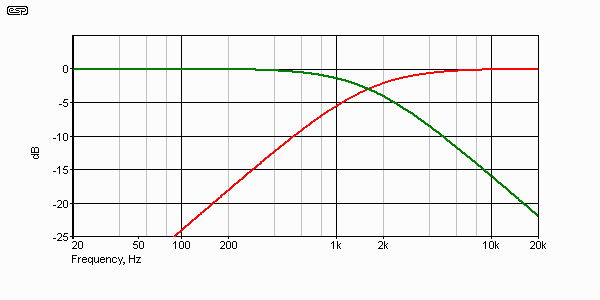

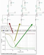
Have a look at a simple gain stage. I have deliberately drawn it so the PSU dropping resistors (R1 / R2 / R3) are 'vertical' to make it obvious that, from the point of view of the triode, they are really part of the anode load resistor.It would be very helpful to myself, FlaCharlie, and probably many others if you could please explain how the capacitor size affects frequency response. As noted by myself and FlaCharlie, there is no obvious audible change to frequency response when the size of the driver tube’s power supply node capacitor is drastically changed.
In the first case there is no PSU bypass cap, so the triode sees a load of 56k+10k = 66k and acheives a flat gain.
In the second case a 1.5uF bypass cap is used. At very low frequencies the cap looks like an open circuit, so the gain is as before. But at high frequencies the cap looks like a short circuit (it 'bypasses'), so the triode sees a load of 56k, so the gain is less. In between is a transition -creating a sort of bass boost. Usually we want this boost to be outside the audible range, or at least small within the audible range.
Making the cap much larger, as in the third case, pushes the boost down lower, so the gain stays flat from 20Hz upwards.
The amount of boost may be small, which is why you may not be able to hear any difference. In this example I threw together it is not even 0.1dB! But hopefully you understand the mechanics. There will be other situations where the frequency response deviation could be larger, esp when coupling transformers get involved. And remember, the power supply is not really a battery as in this ideal example, but a whole series of other filters 'upstream'! You can also play tricks with the cathode bypass cap, to cancel out any boost, but this is just a forum post. It's why people write whole books on these subjects.
Attachments
Last edited:
Yes, the OT dominates the LF response in most reasonable amplifier designs.
Exactly.
With low Rp tubes like a 300B it's really easy to get 4Hz @3-dB with small signal, which means likely 3Hz at least with larger (1W for sure normally) signal with FeSi cores. The permeability is not perfectly constant in gapped FeSi cores and it will increase up to the max rated power if the transformer is well designed. Inductance decreasing before max rated power is reached is not a good design....
Having said this the requirement of 560 uF in my opinion is excessive because one thing is the frequency response at small and medium signal and another thing is at max rated power where the charge-discharge in the PSU will become most critical. In such case 30Hz is normally the "reference" frequency for max output in a well designed transformer without exaggerating with size with EI cores. No lower than 20-25Hz with C cores. For me, personally, it's 30Hz regardless of the core type.....
This means power bandwidth (-3dB) starting from 20Hz.
The "music with massage" is no good for standard loudspeakers anyway (99.9% of them easy, I think). So this is not really a weakness of the typical SE amp.
Best case of 300B amplifier. Let's assume we have a top quality output transformer with HiB C-core and this is 5K and is optimized to work with 80mA DC current to give best inductance and max headroom at 20Hz.
What does it mean optimized for 80 mA max headroom at 20 Hz? It means that the DC induction is taking no less than 50% of the headroom, normally slightly more and the rest is for the signal until the transformer saturates. Let's assume that the max rated power @20Hz is 12.5W. this means we are applying 250V rms signal.
What is the power we can apply at 10Hz and 4 Hz before the transformer saturates? Easy the voltage we can apply is inversely proportional to frequency so we get just over 3W @10Hz and 0.5W at 4Hz....
What's the point of sizing the cap for large persistent transients at 4Hz?
Of course one should not exaggerate in the other direction but as always find a good balance among all requirements.
Because of the signal envelope.What's the point of sizing the cap for large persistent transients at 4Hz?
Attachments
That's because HP and LP are mirror images of each other. With the same R and C, they both give exactly the same -3dB point!
Thank you!Have a look at a simple gain stage. I have deliberately drawn it so the PSU dropping resistors (R1 / R2 / R3) are 'vertical' to make it obvious that, from the point of view of the triode, they are really part of the anode load resistor.
In the first case there is no PSU bypass cap, so the triode sees a load of 56k+10k = 66k and acheives a flat gain.
In the second case a 1.5uF bypass cap is used. At very low frequencies the cap looks like an open circuit, so the gain is as before. But at high frequencies the cap looks like a short circuit (it 'bypasses'), so the triode sees a load of 56k, so the gain is less. In between is a transition -creating a sort of bass boost. Usually we want this boost to be outside the audible range, or at least small within the audible range.
Making the cap much larger, as in the third case, pushes the boost down lower, so the gain stays flat from 20Hz upwards.
The amount of boost may be small, which is why you may not be able to hear any difference. In this example I threw together it is not even 0.1dB! But hopefully you understand the mechanics.
You can do all the same stuff and more, more easily, with PSPICE or TINA TI....
Or with imaginary buckets and long or skinny hoses. SPICE does NOT understand the problem. That is your job. It may not be an easy job; few practical engineering problems are.
Best case of 300B amplifier. Let's assume we have a top quality output transformer with HiB C-core and this is 5K and is optimized to work with 80mA DC current to give best inductance and max headroom at 20Hz.
What does it mean optimized for 80 mA max headroom at 20 Hz? It means that the DC induction is taking no less than 50% of the headroom, normally slightly more and the rest is for the signal until the transformer saturates. Let's assume that the max rated power @20Hz is 12.5W. this means we are applying 250V rms signal.
What is the power we can apply at 10Hz and 4 Hz before the transformer saturates? Easy the voltage we can apply is inversely proportional to frequency so we get just over 3W @10Hz and 0.5W at 4Hz....
What's the point of sizing the cap for large persistent transients at 4Hz?
Of course one should not exaggerate in the other direction but as always find a good balance among all requirements.
45: This is a good point. Loesch uses 4 Hz as an ideal, but does mention that a higher frequency might make more sense in the real world. The ideal criteria set out by his article, 4 Hz and 40 MS in his 300B example, may be unrealistic and completely unnecessary most of the time, and I think that we understand that this is the case. What I want to know is whether or not the method is valid. If so, a person using his method can insert whatever criteria they want.
....Loesch uses 4 Hz as an ideal, but does mention that a higher frequency might make more sense in the real world.....
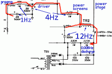
Well, let's see what an utterly practical man might do. This is a Fender amplifier. Leo was an accountant who fixed radios and built a few instrument amplifiers. Work-out the time constants for the several stages of power supply.
Attachments
- Home
- Amplifiers
- Tubes / Valves
- How do you size a capacitor for a B+ node?