Hi All.
I am posting here to ask if anyone knows how to calculate what size a capacitor should be for a given B+ node.
Is there a method that can be used to figure out what value a capacitor should be to properly supply the B+ node for a power tube and the B+ node for a driver tube?
This question is not about having adequate filtering in the supply. Let's assume the supply is well filtered.
Thanks in advance for your replies!
I should add that I am mostly interested in how this applies to single ended triode amplifiers.
Last edited:
.....assume the supply is well filtered....
If the supply IS "well filtered", why do we need ANY cap??
The answer to that may inform the answer to your question.
> power supply bandwidth should be more like
Yes; you can even write math on the complex plane to make the reverse loss exceed the forward gain. I have a reference in deep files somewhere. But I don't think that is the answer wanted here. The cave-man answer is: caps are so cheap we don't ask for a "proper size", but a general notion of a "minimum" size. If we maybe need 13.57uFd, but it takes an hour to confirm that, we may realize that a 40 or 47 uFd is surely ample and cheaper than an hour of brain-work. (The balance changes from DIY to mass production.)
Yes; you can even write math on the complex plane to make the reverse loss exceed the forward gain. I have a reference in deep files somewhere. But I don't think that is the answer wanted here. The cave-man answer is: caps are so cheap we don't ask for a "proper size", but a general notion of a "minimum" size. If we maybe need 13.57uFd, but it takes an hour to confirm that, we may realize that a 40 or 47 uFd is surely ample and cheaper than an hour of brain-work. (The balance changes from DIY to mass production.)
My uncensored thoughts from last year.... for guitar amps, but the problem is the same.....
If you are on AC supply, the filtering needed to kill buzz is "probably" ample to kill motorboating, at least for limited-bass audio systems such as guitar amplifiers.
RDH4 teaches that 2 stages on one node is always stable, so it is uneconomic to have per-stage decoupling. Looking back, many-stage amps tend to run one decoupling node for each two sequential stages.
RCA Tube Manual (RC-14 etc) says "The impedance of the condenser at the lowest frequency amplified should not be more than one-fifth of the impedance of the filter choke or resistor at that frequency" (1/10 better). But this is ambiguous and situational. The resistor may be picked for a voltage drop, not about how much it may couple. "lowest frequency amplified" might be the -3dB freq -or- the unity-gain freq.
Ah-- it was RDH Third with decent dope on decoupling, page 28.
http://tubebooks.org/Books/RDH3.pdf
Page 29 has a big long equation "Condition for Stability". However note that Fig 4 shows the 2nd stage -not- on the same B+ node as 1st and 3rd stages. And it does not have any filter cap on the 1/3 node.
I've lost my Terman but here's an online copy:
https://electrooptical.net/static/oldsite/OldBooks/Terman-RadioEngineersHandbook_1943.pdf
Pg 406-410 (and 405) is the most extensive treatment of positive feedback through the supply that I have seen. His factor D is your decoupling calculator. Even with that modern simplification, his process and digressions is long and does not give me insight.
A blast from the past, 1927-- reading this we are reminded how bad tubes used to be. Much of it is about grid charge-up: tubes in 1927 had high gas and would do odd things with grid resistors. At the end he hits R-C amplifiers with weak battery, and suggests 1uFd caps (large for the time).
www.mcmlv.org/Archive/Amp_Design/Motorboating.pdf
My uncensored thoughts from last year....
Thanks for the links. I read through.
Last edited:
I started this thread because I was told in another thread that the capacitor value I included in the power supply node for a driver tube was "too small". I said okay, how do you work out what it should be? One member linked this article by Loesch, which suggests a relatively simple method of picking the value of the capacitor for the power supply node of a power tube (for single ended amps)...
https://www.diyaudio.com/forums/att...-6v6-el34-singleended-valve-amplifiers-tl-pdf
The last part of the article is where Loesch discusses it. Not caveman, but doable for my caveman brain.
Concerning to me is the article's description of the relationship between an output tube's power supply node capacitance value, and the resistance of the entire supply up to that point. To me, it suggests that arbitrarily picking large capacitance values for power supply nodes may not be the best way to go.
Is using Loesch's method a good way to go?
Last edited:
I'm not sure why you would think that.The reservoir cap is the 1st that feeds a signal tube.
Loesch has a lot of... unusual ideas. You're better getting your info from formal engineering sources than hi-fi-guru-manifestos-on-the-internet. So no. Just make the reactance of the cap at 1Hz a tiny fraction of the wanted impedance in series with the tube. Then use a bigger cap. 47uF covers nearly all situations.Is using Loesch's method a good way to go?
Last edited:

Hi All.
I am posting here to ask if anyone knows how to calculate what size a capacitor should be for a given B+ node.
Thanks in advance for your replies!
I should add that I am mostly interested in how this applies to single ended triode amplifiers.
I try to make this real simple.
This is the part I use in my SET 6v6 Surface amp.
I use 100uf after the EZ-81 ; then a 30/40 choke ; then 100 uf after the choke.
Polarized Clamp Mount Electrolytic Capacitor, 100uF+100uF/500VDC
For me, it depends on the voltage and current draw. A use 220uF in a typical 300V preamp drawing 10mA or so, but only 47uF at 600V.
For the main power section at 300V, I use between 1000uF and 3300uF since it can draw amperes of current and the larger the cap, the smaller the resistor can be for the same filtering.
For the main power section at 300V, I use between 1000uF and 3300uF since it can draw amperes of current and the larger the cap, the smaller the resistor can be for the same filtering.
Merlin told you how to calculate it.
Just make the reactance of the cap at 1Hz a tiny fraction of the wanted impedance in series with the tube. Then use a bigger cap. 47uF covers nearly all situations.
I still don’t see a clear method for working out a cap value. Has it really been 100+ years of winging it?
General questions can only get general answers. Specific questions, with an exact circuit,
component values, and performance requirements, can get specific answers.
Merlin told you how to calculate it.
kodabmx: “Just make the reactance of the cap at 1Hz a tiny fraction of the wanted impedance in series with the tube. Then use a bigger cap. 47uF covers nearly all situations.” What does that look like as a repeatable equation?
Also, isn’t this roughly what Loesch’s method does, as described in the above linked article?
General questions can only get general answers. Specific questions, with an exact circuit,
component values, and performance requirements, can get specific answers.
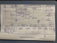
Okay. Using the attached schematic, what is the minimum and ideal value for the capacitor in each node feeding each 30 tube, and what is the process used to derive it? The capacitor in question (F) is shown as a 1.5 uF.
Attachments
Last edited:
- Home
- Amplifiers
- Tubes / Valves
- How do you size a capacitor for a B+ node?