I have a few bench supplies, 15v at 4A or 30v at 2A. Typical bench supplies, with a digital read out of voltage and current. So how could a couple of these be used as a basic valve tester - not transconductance but just DC conditions? And test only triode conditions?
My first thought is to use a glow tube for 150v DC anode voltage. And then use a 100K grid leak + 1K stopper on the grid. One bench supply can be used for the filament voltage, that's easy. So what remains is how to measure voltage/current at the DC operating point?
Can this be done by connecting a bench supply between cathode and ground? You'd set a positive voltage on the cathode at the operating point you want, and then hopefully just read out the current on the meter?
Does this work? Any drawbacks? Any other ideas using bench supplies as above?
.
Last edited:
After sanity checks in an AVO Mk4, I've set up tubes with bench supplies and a couple of DMMs for some "real world" tests. Dial in whatever HT supply desired, with a calibrated 10 ohm resistor in anode circuit, measuring across it with DMM, while applying bias via 100-470kohms, that gets you simple Ia Vg result. For more detail, if you have the gear, make the DMM across the 10 anode resistor a dual display model (I use a Fluke 45), and simultaneously read AC and DC volts while injecting a known AC voltage well away from mains frequency into the grid. Gets you a static DC reading, and Gm with some maths.
I thought about using resistors - that would work by replicating real world operating conditions. But if it's simpler to use a bench supply for biasing the cathode I'd go for that. I could set this up anytime, but I'm just asking for advice first in case there's a problem with doing it this way. Can anyone advise?
For a quick and dirty valve tester you can use an old HT transformer, use the rectified un smoothed HT for the anode, and vary the grid with either a DC supply or a pot on the negative rectified HT. And a nice DC supply for the heater. That is very similar to how the Avo testers work.
It might "work" but it wont say anything about the tube.I have a few bench supplies, 15v at 4A or 30v at 2A. Typical bench supplies, with a digital read out of voltage and current. So how could a couple of these be used as a basic valve tester - not transconductance but just DC conditions? And test only triode conditions?
My first thought is to use a glow tube for 150v DC anode voltage. And then use a 100K grid leak + 1K stopper on the grid. One bench supply can be used for the filament voltage, that's easy. So what remains is how to measure voltage/current at the DC operating point?
Can this be done by connecting a bench supply between cathode and ground? You'd set a positive voltage on the cathode at the operating point you want, and then hopefully just read out the current on the meter?
Does this work? Any drawbacks? Any other ideas using bench supplies as above?
.
Why don't you plug it into an amp that uses it ? DC measurment will tell
if the tube is in decent shape, the sound will tell if it works.
If you are serious , get a uTracer
The uTracer, a miniature Tube Tester / Curve Tracer.
and user you DC supply to power it.
Last edited:
It might "work" but it wont say anything about the tube. Why don't you plug it into an amp that uses it ? DC measurment will tell if the tube is in decent shape, the sound will tell if it works.
I want a tube tester to test a number of tubes. Yes, I can and do put the tube in an amp and read the current on the cathode resistor. But I want a simple tube checker.
My first question is whether I get a proper readout of the cathode current by using a bench supply indicating voltage and current. Is this safe for the tube and the bench supply? As I've said, I could just hook it up and try it but I'd like to know what's going to happen before doing it!
If you want to test a tube DC characteristics, look up in the tube manualI have a few bench supplies, 15v at 4A or 30v at 2A. Typical bench supplies, with a digital read out of voltage and current. So how could a couple of these be used as a basic valve tester - not transconductance but just DC conditions? And test only triode conditions?
My first thought is to use a glow tube for 150v DC anode voltage. And then use a 100K grid leak + 1K stopper on the grid. One bench supply can be used for the filament voltage, that's easy. So what remains is how to measure voltage/current at the DC operating point?
Can this be done by connecting a bench supply between cathode and ground? You'd set a positive voltage on the cathode at the operating point you want, and then hopefully just read out the current on the meter?
Does this work? Any drawbacks? Any other ideas using bench supplies as above?
.
a typical working point. Often it also has a simple drawing of the "typical characteristic". Then make a circuit like it, supply it with the voltages mentioned and measure the elements, compare with the manual.
If you want to test a tube DC characteristics, look up in the tube manual a typical working point. Often it also has a simple drawing of the "typical characteristic". Then make a circuit like it, supply it with the voltages mentioned and measure the elements, compare with the manual.
Hi again. I know all this - I have 2 AVO tube testers and have tested loads of tubes with them, but they both have issues and I'm not going to take them apart myself. I have all the tables of testing conditions etc. and I can look up anything on Franks.
But since nobody seems to know what happens if I use my bench supply as indicated above, then I'll just have to hook it up and hope it works.
My first question is whether I get a proper readout of the cathode current by using a bench
supply indicating voltage and current. Is this safe for the tube and the bench supply?
Yes, but most bench supplies won't give an accurate low current reading.
A DVM can read the voltage drop across a 10R 1% cathode resistor accurately.
For example, 10mA through 10R gives 100mV.
But since nobody seems to know what happens if I use my bench supply as indicated above, then I'll just have to hook it up and hope it works.
Everybode DOES know, it's just unclear what you are asking.
Of course a bench supply will work, a tube tester is nothing but a machine containing several very simple, low performance supplies and a meter. You can use bench supplies and meters to do the same and more.
Just post an example of what tube you want to test and what conditions you want to test it under and what you want to measure. I'll be happy to provide you with an actual schematic showing the supplies and meters.
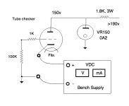
Here's diagram to make it clearer......
I'll get the operating points from the tube data sheets on Frank's site.
I'm using a nominal 150v which should give a general idea with most tubes.
I intend to test mainly smaller tubes, so current of approx. 5 to 10mA
I'll get the operating points from the tube data sheets on Frank's site.
I'm using a nominal 150v which should give a general idea with most tubes.
I intend to test mainly smaller tubes, so current of approx. 5 to 10mA
Attachments
Last edited:
Yes that will work fine. If your >190V is a bench supply, no regulator tube is necessary, just adjust the supply to 150V or whatever other voltage you want.
I would put the other supply in the grid, not the cathode. Just for simplicity. The way you have it shown, every time you adjust the cathode supply you change the Vak.
And careful to turn on the grid/cathode supply before the anode supply.
I would put the other supply in the grid, not the cathode. Just for simplicity. The way you have it shown, every time you adjust the cathode supply you change the Vak.
And careful to turn on the grid/cathode supply before the anode supply.
Yes that will work fine. If your >190V is a bench supply, no regulator tube is necessary, just adjust the supply to 150V or whatever other voltage you want. I would put the other supply in the grid, not the cathode. Just for simplicity. The way you have it shown, every time you adjust the cathode supply you change the Vak. And careful to turn on the grid/cathode supply before the anode supply.
Indeed - need to turn on the bias voltage before switching on the HT. No - I don't have a bench supply over 30v.
It hadn't struck me that the cathode voltage changes the Vak. That could be factored into the operating point, a bit tedious. But if the bias voltage is small it wouldn't make much difference to a quick and dirty test. If you bias the grid, however, how will you get a read-out of the current? A small resistor in the cathode connected to a DMM or what?
So how could a couple of these be used as a basic valve tester - not transconductance but just DC conditions? And test only triode conditions? ..................Any other ideas using bench supplies as above?
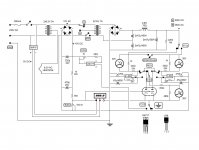
This is the setup I use to determine the DC conditions of any tube. The bench supply can source a regulated voltage of 200V - 325V. There is also a 6.3V filament supply. I use a small scrap chassis for the tube under test fitted with an assortment of sockets. So for a triode under test, I am interested in learning what plate voltage and current will be for any given bias point.
Since I have several direct coupled amps, the plate voltage is important since it will bias the following tube. Naturally, you could also compare the operating points of the tube under test with the tube manual expected values.
So if the tube is diode biased, for instance, there will be a 10r resistor in series with the diode to measure current. I would set the plate voltage to the that required to bias the following tube (there is no need for a load, but if the plate voltage is to be less than 200V I need to use a resistor load to bring the plate voltage to the correct value) and then read the current. So I would be matching the tubes for a specific current in this example with the plate voltage and bias fixed.
Naturally, one could vary any of the operating point conditions e.g., bias, current or voltage to compare to the tube manual operating conditions.
Attachments
Use one of these to generate the HV from 15V Adjustable ZVS Capacitor High Voltage Boost Converter Board DC DC DC 8 32V to 45~390V/DC 8 32V to +-45V 390V Step Up Boost Module| | - AliExpress
It hadn't struck me that the cathode voltage changes the Vak.That could be factored into the operating point, a bit tedious. But if the bias voltage is small it wouldn't make much difference to a quick and dirty test. If you bias the grid, however, how will you get a read-out of the current? A small resistor in the cathode connected to a DMM or what?
Simply an ammeter (DMM) between cathode and ground. That's what they do. Measure current. Just connect it securely.
You don't want to rely on the ammeter on a bench supply anyway, unless you calibrate it. The accuracy would be questionable unless it's a high end instrument grade supply.
Last edited:
I have a few bench supplies, 15v at 4A or 30v at 2A. Typical bench supplies, with a digital read out of voltage and current. So how could a couple of these be used as a basic valve tester - not transconductance but just DC conditions? And test only triode conditions?
My first thought is to use a glow tube for 150v DC anode voltage. And then use a 100K grid leak + 1K stopper on the grid. One bench supply can be used for the filament voltage, that's easy. So what remains is how to measure voltage/current at the DC operating point?
Can this be done by connecting a bench supply between cathode and ground? You'd set a positive voltage on the cathode at the operating point you want, and then hopefully just read out the current on the meter?
Does this work? Any drawbacks? Any other ideas using bench supplies as above?
.
This book arrived on my doorstep a few days ago. It is a great book! I didn't expect much but when I got it, I found it to be very advanced, yet its main topic is "simple" tube characteristics. Many schematics on doing just what you're asking. Understanding characteristics and load lines has been a challenge for me, but seeing tubes in the context of these test Circuits is opening up things for me. Highly recommended!

Tube characteristics are normally quoted Common Cathode.
You can measure however you want, and do arithmetic. But common sanity says: ground (zero volts) the cathode and read everything else relative to that.
The obvious tool is a 0-300V DC power supply with an ammeter. The classic TUBE workbench supply also has a negative 0-50V bias supply. These two and a heater supply is all you need for triodes. Pentodes will want a second supply for screen.
Tube characteristics are normally quoted Common Cathode. You can measure however you want, and do arithmetic. But common sanity says: ground (zero volts) the cathode and read everything else relative to that. The obvious tool is a 0-300V DC power supply with an ammeter. The classic TUBE workbench supply also has a negative 0-50V bias supply. These two and a heater supply is all you need for triodes. Pentodes will want a second supply for screen.
A high voltage bench supply would be useful, but they're expensive! I like the idea of the Chinese voltage multiplier fed from a 0-30v supply.
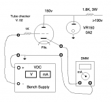
Revised schematic below. On my bench supply there's no measurable resistance between positive and negative terminals. Tube data always specifies a maximum value grid leak resister to avoid oscillation, so what do we do about that? Put a resistor across the terminals or leave it, or what?
Attachments
Last edited:
- Home
- Amplifiers
- Tubes / Valves
- Simple tube tester using bench supplies?