Hi,
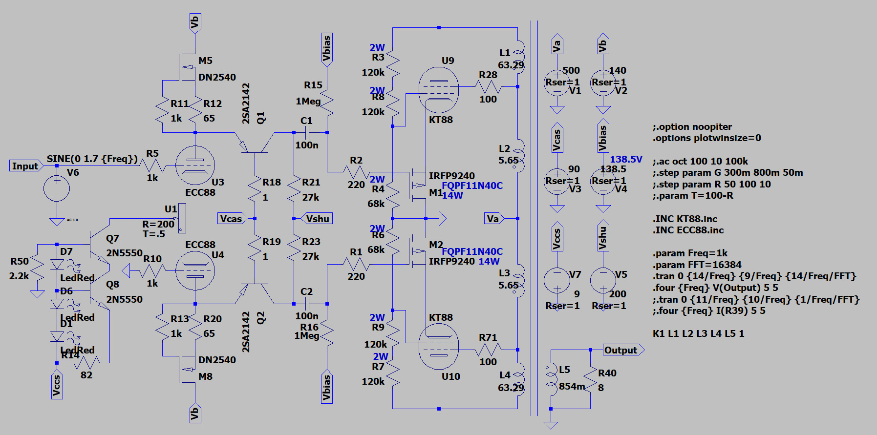
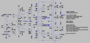
I would like to propose you this design for a KT88 push pull amp.
The phase inverter is two Rod Coleman's Shunt Cascode Driver with a CCS on the cathodes of the two triodes, whilst the power amp is the Pmosfet cathode-driven 22% anode-grid local feedback configuration already used by TubeLab_com for his UNSET, plus 23% UL.
I attach here the schematic in jpg and LTSpice format.
I already have the output transformers, and that would be the only limit.
Any comment is really appreciated.
Thanks in advance,
Roberto
Attachments
You have the bulk of the inductance between the screen and anode, so your kt88 is mostly a triode. I thought that the purpose of ultralinear was to put only a small (20-43) percentage between the screen and anode - or have I got that the wrong way around?
kind regards
Marek
kind regards
Marek
You have the bulk of the inductance between the screen and anode...
edit:- I take that back, but doesn't such a low inductance% imply well below 20% turns tap?
Last edited by a moderator:
Any comment is really appreciated.
Well, tell us what this design accomplishes, what was the design goal and what were the results. How it is better than something else. Otherwise my only comment is that it's more complex than it needs to be

For an LTP driving PP outputs, the shunt cascode can be simplified without significantly sacrificing performance. I have a PP amp with LTP shunt cascode. B+ for the driver stage is regulated (comes from a regulated screen supply for the output tubes), which allows the following changes:
-Rod Coleman's drivers were designed for SET output, and have quite elaborate circuitry for the cascode reference voltage. For PP a simple voltage divider bypassed to B+ is sufficient. No hum/noise can be heard at the speakers.
- The CCS's on the LTP anodes can be replaced with a simple resistor. Given the LTP anodes are at a fixed voltage (or close to it), a resistor acts as a CCS with a fixed B+
- output DC can be set at ~1/2 the cascode reference voltage by adjusting the LTP current, assuming you've done the maths right with the anode resistor value. Need reasonably well matched triodes or there could be significant DC imbalance.
As far as advantages go, the shunt cascode does allow for enough gain and swing in a single stage to drive the outputs, with lower B+ voltage requirement. Although if you have enough B+ voltage you can achieve the same thing with a normal cascode LTP, especially if you use a BJT for the upper device. The UNSET configuration advantages are discussed elsewhere (triode-like curves with low output impedance, ability to extract more power than a straight triode connection) but at the very least it provides an interesting diversion")
-Rod Coleman's drivers were designed for SET output, and have quite elaborate circuitry for the cascode reference voltage. For PP a simple voltage divider bypassed to B+ is sufficient. No hum/noise can be heard at the speakers.
- The CCS's on the LTP anodes can be replaced with a simple resistor. Given the LTP anodes are at a fixed voltage (or close to it), a resistor acts as a CCS with a fixed B+
- output DC can be set at ~1/2 the cascode reference voltage by adjusting the LTP current, assuming you've done the maths right with the anode resistor value. Need reasonably well matched triodes or there could be significant DC imbalance.
As far as advantages go, the shunt cascode does allow for enough gain and swing in a single stage to drive the outputs, with lower B+ voltage requirement. Although if you have enough B+ voltage you can achieve the same thing with a normal cascode LTP, especially if you use a BJT for the upper device. The UNSET configuration advantages are discussed elsewhere (triode-like curves with low output impedance, ability to extract more power than a straight triode connection) but at the very least it provides an interesting diversion
I developed the technology used in the output stages to solve several real issues. I can't say much about the rest of the circuit, or the use of the output stage in an ultralinear configuration, but if it behaves as it does in pure pentode mode the output impedance and THD will be lowered significantly.
My original design was intended to allow operation of a TV horizontal sweep (line output) tube in triode mode without violating its screen grid voltage rating. This was accomplished with a single positive voltage power supply and a simple Zener with mosfet buffer voltage source for the 170 volt screen supply. The direct feedback from the plate to the control grid creates the triode like curves. The picture shows some hand traced curves from a small sweep tube using this technique.
More info is here:
UNSET is coming?
Attachments
George, I do remember that thread and a great one it is. I'm having trouble connecting that concept here. Can you comment on how you see it being beneficial (or not) to a KT88 class tube in pentode, in AB1? Not necessarily practical results, just the theoretical concept of why I would want to do it.
Well, tell us what this design accomplishes, what was the design goal and what were the results. How it is better than something else. Otherwise my only comment is that it's more complex than it needs to be
Results in simulation is 80 Wrms with less than 1% THD, and only low order harmonics (2nd, 3rd) until very high wattages.
The design goal is to drive KT88s with 22% a-g1 local feedback (plus 23% UL) with one single gain stage, keeping the distortion low and with a reasonable DF around 3.5 without using global feedback. Also, the goal is to have higher Wrms whilst making KT88 work at lower plate voltages (around 400V a-k), so with more A class available.
Thanks, power supply "complications" were something I was worried about, indeed! This way I can configure a common positive-bias supply with three pots per channel (cascode reference, and two KT88), then a beefy negative voltage for the output resistor and PI's LT.-Rod Coleman's drivers were designed for SET output, and have quite elaborate circuitry for the cascode reference voltage. For PP a simple voltage divider bypassed to B+ is sufficient. No hum/noise can be heard at the speakers.
Thanks, I will try it too.- The CCS's on the LTP anodes can be replaced with a simple resistor. Given the LTP anodes are at a fixed voltage (or close to it), a resistor acts as a CCS with a fixed B+
I've indeed set the current through the output resistors to set the no-signal voltage halfway inbetween the negative reference voltage of the resistor and the cascode reference voltage, to get maximum swing. The resistor reference is set negative in order to achieve a higher swing (thanks Rod for this tip).- output DC can be set at ~1/2 the cascode reference voltage by adjusting the LTP current, assuming you've done the maths right with the anode resistor value. Need reasonably well matched triodes or there could be significant DC imbalance.
The reason why I used this configuration is that allowes me to drive the KT88 with very low THD, but I'll try your suggestion here below (I'm indeed in contact with Prasi to experiment a cascoded LTPI with ECC83 on bottom and BJT on top for the Baby Huey EL34 project, in order to better drive tubes demanding more swing to be properly driven).As far as advantages go, the shunt cascode does allow for enough gain and swing in a single stage to drive the outputs, with lower B+ voltage requirement.
Thanks, I will try it again. Am I right saying that most probably it would perform better with a resistor in parallel to the BJT+collector's load? In order to increase the current through the triode and improve its linearity.Although if you have enough B+ voltage you can achieve the same thing with a normal cascode LTP, especially if you use a BJT for the upper device.
The UNSET configuration advantages are discussed elsewhere (triode-like curves with low output impedance, ability to extract more power than a straight triode connection) but at the very least it provides an interesting diversion
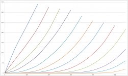
Yes, this post by Spreadspectrum made me go for KT88 with 20% a-g1 feedback: The point of an 845, 211, 805 amp?
300B curves (yellow) KT88 triode-connection curves (blue) and KT88 20% feedback curves (magenta).
Thank you very much for having written here! I really appreciate! From simulations I've done, I have a DF of 3,5 on 8 Ohms and a THD as follows:I developed the technology used in the output stages to solve several real issues. I can't say much about the rest of the circuit, or the use of the output stage in an ultralinear configuration, but if it behaves as it does in pure pentode mode the output impedance and THD will be lowered significantly.
at 1 Wrms:
Code:
Harmonic	Frequency	 Fourier 	Normalized	 Phase  	Normalized
 Number 	  [Hz]   	Component	 Component	[degree]	Phase [deg]
    1   	1.000e+03	3.881e+00	1.000e+00	   -0.83°	    0.00°
    2   	2.000e+03	3.297e-04	8.494e-05	  -93.53°	  -92.70°
    3   	3.000e+03	1.638e-04	4.221e-05	    2.67°	    3.50°
    4   	4.000e+03	4.869e-06	1.255e-06	 -179.33°	 -178.50°
    5   	5.000e+03	3.900e-06	1.005e-06	 -179.50°	 -178.66°
    6   	6.000e+03	3.249e-06	8.372e-07	 -179.95°	 -179.11°
    7   	7.000e+03	2.782e-06	7.168e-07	  179.97°	  180.80°
    8   	8.000e+03	2.429e-06	6.259e-07	 -179.81°	 -178.98°
    9   	9.000e+03	2.158e-06	5.561e-07	 -179.97°	 -179.14°
Total Harmonic Distortion: 0.009488%(0.009452%)
at 30 Wrms:
Code:
Harmonic	Frequency	 Fourier 	Normalized	 Phase  	Normalized
 Number 	  [Hz]   	Component	 Component	[degree]	Phase [deg]
    1   	1.000e+03	2.147e+01	1.000e+00	   -0.84°	    0.00°
    2   	2.000e+03	1.010e-02	4.701e-04	  -92.06°	  -91.22°
    3   	3.000e+03	3.034e-02	1.413e-03	    3.48°	    4.32°
    4   	4.000e+03	5.895e-05	2.745e-06	 -111.89°	 -111.05°
    5   	5.000e+03	5.038e-04	2.346e-05	 -157.07°	 -156.23°
    6   	6.000e+03	1.503e-05	7.000e-07	  175.45°	  176.29°
    7   	7.000e+03	7.843e-05	3.652e-06	    5.28°	    6.12°
    8   	8.000e+03	1.099e-05	5.119e-07	 -178.45°	 -177.61°
    9   	9.000e+03	1.993e-05	9.280e-07	  179.67°	  180.51°
Total Harmonic Distortion: 0.148933%(0.148930%)
at 80 Wrms:
Code:
Harmonic	Frequency	 Fourier 	Normalized	 Phase  	Normalized
 Number 	  [Hz]   	Component	 Component	[degree]	Phase [deg]
    1   	1.000e+03	3.600e+01	1.000e+00	   -0.87°	    0.00°
    2   	2.000e+03	2.858e-02	7.938e-04	  -91.97°	  -91.10°
    3   	3.000e+03	3.002e-01	8.339e-03	    2.77°	    3.64°
    4   	4.000e+03	4.664e-04	1.295e-05	  -89.93°	  -89.07°
    5   	5.000e+03	7.560e-02	2.100e-03	 -178.23°	 -177.36°
    6   	6.000e+03	1.138e-04	3.161e-06	  110.90°	  111.76°
    7   	7.000e+03	2.440e-02	6.778e-04	   -1.28°	   -0.41°
    8   	8.000e+03	7.819e-05	2.172e-06	  -99.44°	  -98.57°
    9   	9.000e+03	4.939e-03	1.372e-04	  177.15°	  178.02°
Total Harmonic Distortion: 0.866358%(0.866358%)Indeed your design is smarter than mine, as I would expect. I have a quartet of matched KT88 and two output transformers with 4 kOhm Raa and 23% UL taps, a power transformer with proper voltages, so I tried to design an amp with good performances using those elements.My original design was intended to allow operation of a TV horizontal sweep (line output) tube in triode mode without violating its screen grid voltage rating. This was accomplished with a single positive voltage power supply and a simple Zener with mosfet buffer voltage source for the 170 volt screen supply.
It is incredible how this local feedback, that permits to have triode-like curves with pentode-like gains, has been abandoned for decades by most people after the RCA amp.The direct feedback from the plate to the control grid creates the triode like curves.
I'm already following the thread with much curiosity! Thanks!More info is here:
UNSET is coming?
Waiting for George's reply, I give you my motivations:George, I do remember that thread and a great one it is. I'm having trouble connecting that concept here. Can you comment on how you see it being beneficial (or not) to a KT88 class tube in pentode, in AB1? Not necessarily practical results, just the theoretical concept of why I would want to do it.
- triode-like curves (see SpreadSpectrum's plots above) with more gain and lower Rp;
- lower THD than pentode or UL;
- more current through the KT88 to allow more class A;
- together with UL, good DF without using gnfb;
- more available power (Pmosfet in source follower mode takes part to the total amount of avaliable power).
This gives me two ideas:If you have enough B+ voltage you can achieve the same thing with a normal cascode LTP, especially if you use a BJT for the upper device.
The first one is to treat the normal cascode as a pentode, so apply the a-g1 feedback as well to linearize it, then cathode drive it.
The second one is based on this thread by Spreadspectrum (https://www.diyaudio.com/forums/tub...low-distortion-a2-dht-se-amp-prototype.html): ccs load the two pentodeish normal-cascodes and use the extra gain to apply gnfb and reach very high DF.
I have to say that the first option is something I can try to simulate together with the normal-cascode, to choose which one to build. The second most probably will not be my choice, as real high DF is not something I'm very interested into, at least with my speakers. Others could be more interested.
George, I do remember that thread and a great one it is. I'm having trouble connecting that concept here. Can you comment on how you see it being beneficial (or not) to a KT88 class tube in pentode, in AB1? Not necessarily practical results, just the theoretical concept of why I would want to do it.
Most of my time with this technology has been spent on tubes that have a low Vg2 max because that was the reason for it in the first place. I have a little guitar amp about half built (the power amp half) that extracts 20 watts from a pair of 50C5 radio tubes. I keep the screen grid at the 120 volt spec, but feed the plate about 340 volts. To prove it's worth I set the signal generator for 20 watts output one evening, and the amp was happily reading 20.04 watts the next morning.
The KT88 can run with B+ on it's screen grid so it's easy to run it in triode mode. Still, you only get ONE kind of triode. The UNSET / CED tech allows you to get an infinitely adjustable triode by adjusting the ratio of the plate to grid voltage divider.
It is also possible to use the same concept to turn a high Mu triode into a low Mu triode, although I have only tried this in the mind of the simulator. I do have a bunch of those "useless" regulator beam triodes (6HV5, 6JD5...) with a Mu of 300. So far the only thing I have made with them is power oscillators and TV jammers.
Beam triodes, KT88's, DHP's and a few other oddities are on my list of tubes to try now that I have more than one board to play with.
The first one is to treat the normal cascode as a pentode, so apply the a-g1 feedback as well to linearize it, then cathode drive it.
I just use a pentode for the first tube, apply Plate to G1 feedback, then cathode drive it. Note that some of my push pull amps also apply feedback from the output tube plate to the screen grid of the driver.
Here is the schematic of the current UNSET board. All the funny stuff around the output tube is a jumper matrix allowing the use of any octal tube, or any tube with the use of off board sockets.
Attachments
Thanks, I will see if I can apply the same here in the normal-cascode scenario. The driver pentode is resistor loaded to have some "flavour" on the sound vs a CCS that would be "too clean"? I remember you talking about a switchable triode-UL amp years ago, where "some distortion" was preferred in low to medium volume settings.I just use a pentode for the first tube, apply Plate to G1 feedback, then cathode drive it. Note that some of my push pull amps also apply feedback from the output tube plate to the screen grid of the driver.
Great! Thanks again! I notice that I've forgotten a safety diode on the pmosfet, but the bias setting is similar to what I wanted to do, and to what the cascode reference voltage would be as well.Here is the schematic of the current UNSET board. All the funny stuff around the output tube is a jumper matrix allowing the use of any octal tube, or any tube with the use of off board sockets.
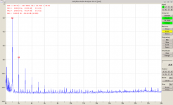
When the cascode voltage-reference [Vcasc] is well-implemented, the shunt cascode voltage amplifier/driver can give results worthy of attention:
The output given below is a real measurement for a single shunt cascode with Russian 6Э5П (6E5P) at Ua=200V, Ia=35mA, and the load resistance is 27k, as per your circuit.
The output is ca. 50V rms, 149V peak-peak. A regular cadence to the harmonics, like this one, is the sign of good sound, IME.
The output given below is a real measurement for a single shunt cascode with Russian 6Э5П (6E5P) at Ua=200V, Ia=35mA, and the load resistance is 27k, as per your circuit.
The output is ca. 50V rms, 149V peak-peak. A regular cadence to the harmonics, like this one, is the sign of good sound, IME.
Attachments
One thing I don't like...
If the Shunt Cascode's current source is replaced by resistors [R12, R20 in this case] the performance is degraded. It's because the power supply rejection is poor like this. To get the performance back to the level with a current source, a regulated supply must be used. Much more complicated than a current source.
If the Shunt Cascode's current source is replaced by resistors [R12, R20 in this case] the performance is degraded. It's because the power supply rejection is poor like this. To get the performance back to the level with a current source, a regulated supply must be used. Much more complicated than a current source.
- Home
- Amplifiers
- Tubes / Valves
- Shunt Cascode Driver meets UNSET for Push-Pull