(title inspired by Bas Baby Huey thread)
I've been looking for a ~30W P-P amp, and leaning towards the CB modified Mullard 5-20 (aka Mullard 4-30).
Lundahl Transformers • Old fashioned 30W Push Pull amplifier
I'm not great at P2P and so want to recreate one of the PCB's that originally existed, the CB or Elektor.
My preference is for a single stereo amp, to reduce cost and size.
The proposed Lundahl set LL1663/PP and LL1669A power trans. are reasonably priced.
The LL1669A seems like it could easily power a stereo build.
I like the way Elektor set it up, looks like a ST-70, although I think I would keep the EL-34's off board on chassis mount sockets.
As part of the PCB design, I'll incorporate Claus comments from his 2018 "revisited" document.
A few initial points:
1) Any thoughts on which PCB design is a better starting point?
2) I may use the Elektor PSU PCB since it was intended for a stereo build. One thing that I'm a bit confused about is that it seems like it does not have any PS filtering at all?
3) There was a thread from last year by a member here who built this amp with the Elektor PCB's and had some hum issues with AC heaters... perhaps there is a flaw in the Elektor PCB in that regard.
any other comments welcome
Attachments

....it seems like it does not have any PS filtering at all?....
C11, C10?
Page 20 in the building instructions on the Lundahl site show a choke. (5-10H 180mA) Elektor never bothered with it.
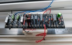
Turret boards are a very simple way to make point to point easier. They are like reconfigurable PCB's. This is the heart of my modified 5-20. I did briefly have it configured as a cathode biased version of the Claus Byrith 4-30 so if it's of any help, I have the turret board layout for it.
Turret boards are a very simple way to make point to point easier. They are like reconfigurable PCB's. This is the heart of my modified 5-20. I did briefly have it configured as a cathode biased version of the Claus Byrith 4-30 so if it's of any help, I have the turret board layout for it.
Attachments
Hi, thanks for the info and nice board!
I see now the choke you mention, it was written as optional.
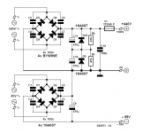
I'm confused about the CT in the PSU schematic.
Besides that the recommended LL1669A doesn't provide a CT, how is the CT being using along with the bridge rectifier?
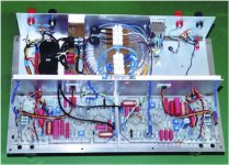
Aside from that, do you have a picture of your completed amp? That would also help get an idea of what the finished chassis would look like without PCBs.
I see now the choke you mention, it was written as optional.
I'm confused about the CT in the PSU schematic.
Besides that the recommended LL1669A doesn't provide a CT, how is the CT being using along with the bridge rectifier?
Aside from that, do you have a picture of your completed amp? That would also help get an idea of what the finished chassis would look like without PCBs.
Attachments
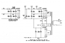
itsikhefez; said:Besides that the recommended LL1669A doesn't provide a CT, how is the CT being using along with the bridge rectifier?
It is just keeping the voltage between the two capacitors pairs (220uF and 47uF) equal. I.e. they both have 1/2 the B+ across them.
Series caps do not necessarily 'share' the voltage across them equally.
On your circuit the voltage balance between the 470uF caps is provided by the R1 and R2 / D9 and D10.
It's not finished yet as I'm yet to sort a proper chassis so the wiring has been left slightly long. I changed the design so that the cathode bias part of the board was separate.Hi, thanks for the info and nice board!
I see now the choke you mention, it was written as optional.
I'm confused about the CT in the PSU schematic.
Besides that the recommended LL1669A doesn't provide a CT, how is the CT being using along with the bridge rectifier?
Aside from that, do you have a picture of your completed amp? That would also help get an idea of what the finished chassis would look like without PCBs.

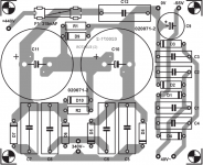
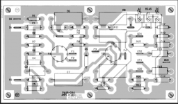
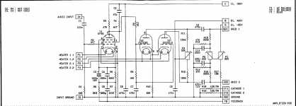
I've been slowly designing the PCB layout based on the Appendix documents, and there is some discrepancy between the schematic and the board.
In particular, one schematic has R17 as a 15K resistor to ground from P1. This part appears on the silkscreen but its not very clear how its routed... P1 doesn't go through it at all.
Thoughts?
In particular, one schematic has R17 as a 15K resistor to ground from P1. This part appears on the silkscreen but its not very clear how its routed... P1 doesn't go through it at all.
Thoughts?
Attachments
Here's one place ... AliExpress will probably be a good source too.
Turret board
Turret board
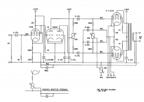
Schematic in Post # 8 has 3 potentiometers (4 if you count the variable negative feedback).
Just use the very highest quality potentiometers, since they all carry DC current, and they affect the bias and voltages on the tubes.
Any bad connection, any noisy connection, or any intermittent connection of the potentiometer Wiper will cause problems.
If you use matched EL34 tubes; individual self bias 'resistor and individual bypass capacitors' in each cathode, that will get rid of the need for 2 of those potentiometers.
True, that will reduce the power output slightly, because the self bias voltage "robs" from the total B+ voltage.
If you use fixed negative feedback resistors, that will get rid of one of those potentiometers.
If you use a real current source in the phase splitter cathodes, that will get rid of one of those potentiometers.
That totals 0 potentiometers.
The above are just my opinions, and how I would do it.
Of course, some are not willing to tradeoff perhaps 1dB less power output, for a more reliable circuit that is also intrinsically automatically adjusted, no potentiometers necessary.
Last edited:
Schematic in Post # 8 has 3 potentiometers (4 if you count the variable negative feedback).
Just use the very highest quality potentiometers, since they all carry DC current, and they affect the bias and voltages on the tubes.
Any bad connection, any noisy connection, or any intermittent connection of the potentiometer Wiper will cause problems.
If you use matched EL34 tubes; individual self bias 'resistor and individual bypass capacitors' in each cathode, that will get rid of the need for 2 of those potentiometers.
True, that will reduce the power output slightly, because the self bias voltage "robs" from the total B+ voltage.
If you use fixed negative feedback resistors, that will get rid of one of those potentiometers.
If you use a real current source in the phase splitter cathodes, that will get rid of one of those potentiometers.
That totals 0 potentiometers.
The above are just my opinions, and how I would do it.
Of course, some are not willing to tradeoff perhaps 1dB less power output, for a more reliable circuit that is also intrinsically automatically adjusted, no potentiometers necessary.
Thanks for the tips. I want to start off with the design as-is, and once I have that finalized I will will slowly incorporate modifications as needed.
I think I'd rather keep the first 2 pots that will allow for unmatched tubes.
I am using a fixed resistor for NFB so no pot there.
The current source for phase splitter sounds interesting
The bias pot which goes to -60V can be wound right to 0V which will pop your EL34's. I would suggest replacing it with 10K and a fixed 10K to ground so you cannot get above -30V bias. This happened on another thread.
It is done this way on the first schematic on post #8. It is a 20K pot with 15K fixed resistor. I will do it this way.
Need some assistance on resistor rating. In the original article, CB wrote that he used 2W resistors for everything (except the 10R cathode resistors which are 5W).
I'd rather use 1/2W resistors where possible, and 2W resistors where needed.
Do I have this marked correctly?
Green = 2W
Red = 5W
Blue = 1/2W
I'd rather use 1/2W resistors where possible, and 2W resistors where needed.
Do I have this marked correctly?
Green = 2W
Red = 5W
Blue = 1/2W
Attachments
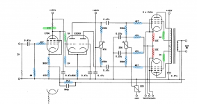
I would suggest a few changes to what you propose.
1. The 1k “grid stopper” between EF86 and 12ax7 could be 1/2w.
2. I would prefer the 150k load resistors for the 12ax7 to be 2w.
3. The 82k tail resistor should be 2w, as I think it is probably dissipating close to 1/2w
4. The 10R current measuring resistor in the EL34 cathodes is dissipating only about 0.025 watts. Due to the cathode heater nearby make that a 2 watt resistor, but a 1/2 watter will probably be fine.
Thank you Francois! I will make the adjustments.
This is also needed so that the appropriate resistor sizes are used on the PCB.
Regarding the 10R, this is what the documentation says:
"The two 10 W resistors in the cathodes of the output valves are used to facilitate all adjusting of current and balance and it is imperative that they are stable and equal to a very close match. I recommend 5W wirewound types and you must match them yourself"
Not sure entirely about the consideration but I went with Mills MRA-5 for these, as they have fairly good tolerances.
I see, mr. Byrith was concerned about accuracy and stability for these current measuring resistors, and rightly so. Mills MRA-5s would be stable and accurate if selected, so a very good choice if the budget allows. More frugal folks could make do with matched resistors, and checking the values annually with a good multimeter.
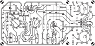
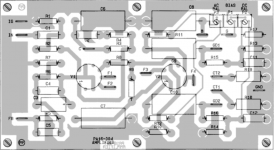
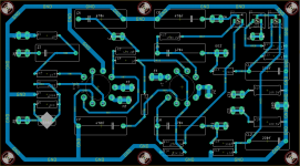
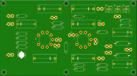
This has been going slowly but first draft of the PCB is ready.
It is basically copied from CB's documentation with minor adjustments, including removal of the parts for the original Mullard that were redundant in this design.
I'm not entirely sure about the ground that goes all around, CB had pours on both sides of the PCB's.
Any other feedback or comments welcome.
(original PCB added for reference)
Attachments
- Home
- Amplifiers
- Tubes / Valves
- Oh no... another Mullard 4-30 thread