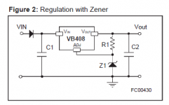
I was looking at data sheets for the LR8 high voltage/low current regulator IC and came across one for the discontinued VB408. In that data sheet I found an interesting little circuit (attached).
Like an LM317, these regulator ICs set their output voltage with a voltage divider from the IC OUT pin to ground, with R1 from the OUT pin to the ADJ pin, R2 from the ADJ pin to ground.
This attached circuit, instead of using an R2, uses a zener string to set the output voltage, retaining R1. The value of R1 needs to be chosen to supply necessary current to the zener string, maybe 10mA. The LR8 only needs minimum 10uA from its OUT pin to its ADJ pin.
The data sheet says,
I'm sure this can be done with an LR8 too. A string of four 75V zeners and one 51V zener should get Vout = 350V.
The expected load on the LR8 would be 35V dropped across it (385V input, 350V out) at 7.5mA, so 263mW dissipation.
Stupid idea?
--
Like an LM317, these regulator ICs set their output voltage with a voltage divider from the IC OUT pin to ground, with R1 from the OUT pin to the ADJ pin, R2 from the ADJ pin to ground.
This attached circuit, instead of using an R2, uses a zener string to set the output voltage, retaining R1. The value of R1 needs to be chosen to supply necessary current to the zener string, maybe 10mA. The LR8 only needs minimum 10uA from its OUT pin to its ADJ pin.
The data sheet says,
The output voltage can also be set by a zener diode put between the adjustment pin and ground (Figure 2). The biasing current of the zener is properly chosen by R1 resistor. The zener diode improves the ripple rejection and reduces the value of the worst case output voltage error. In this case the output voltage is given by
Vout = Vref+Vz
I'm sure this can be done with an LR8 too. A string of four 75V zeners and one 51V zener should get Vout = 350V.
The expected load on the LR8 would be 35V dropped across it (385V input, 350V out) at 7.5mA, so 263mW dissipation.
Stupid idea?
--
Attachments
Can be done, if attention is paid to startup/power down transients.
Would need some protection diodes, etc. An example with a LM317:
https://booksite.elsevier.com/samplechapters/9780750686266/Sample_Chapters/02~Chapter_1.pdf
Would need some protection diodes, etc. An example with a LM317:
https://booksite.elsevier.com/samplechapters/9780750686266/Sample_Chapters/02~Chapter_1.pdf
Last edited:
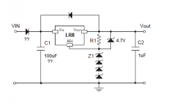
From what I can tell (and bearing in mind that I'm an uneducated tinkerer, definitely not an electrical engineer!), it looks like
1. Since the LR8 is rated for 450V at up to 10mA, popping it because of high voltage is not the problem if the raw supply is about 360V. (Unlike the LM317, which is limited to 37V In-Out.)
2. Reverse voltage would be an issue. The LR8 data sheet shows a 'typical application circuit' with an unspecified diode in parallel, with the diode's cathode to the LR8 IN pin and the anode to the LR8 OUT pin. Would that need to be a rectifier like a 1N4004? I don't see why a zener would be necessary as is needed for the LM317.
3. I'd think a lot of ripple voltage at the IN pin could zap the thing. The raw supply to IN should be well filtered. That's not a problem.
4. Too high value capacitors would be a problem though. The data sheet recommends only 1uF on the output. It doesn't mention anything about capacitance from IN to ground.
So, with an LR8, would this (attached) be enough protection?
(Is that series diode to the IN pin necessary? I never see that used...)
--
PS: The intended application is the B+ for a single 12AX7 drawing 2mA plate current, and a MOSFET source follower drawing 5mA, for a total of about 7mA. The raw HV supply could be as little as 360V. The desired Vout is 330V.
Attachments
Last edited:

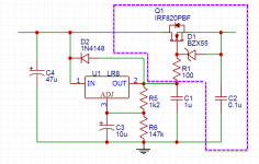
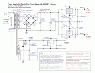
I read this article about using an LR8 with a pass transistor. And then used a version with a mosfet to provide 320 volts DC to a preamp and crossover that uses 4 6SN7 tubes.
Works very well.
Steve
Works very well.
Steve
Attachments
Thanks Steve.
In that circuit, it looks like the LR8 is set to 150V at its OUT pin, and I guess the IRF820 is stacked on top for the additional 170V to make the 320V output?
Four 6SN7s would draw something like 20mA to 35mA of plate current. The article mentions the described circuit to be good for up to 100mA. I'm not asking the LR8 to do anything near that. Only 7mA, max.
The zener string would provide a 'stabilized' voltage, and then the LR8 sits on top of that. I figure that could be a pretty effective and very simple circuit for a high voltage/low current application like a plate supply for a single 12AX7.
--
Question:
Is a diode necessary in parallel to R1?
If so, what kind?
My (limited) understanding is that a diode across R1 is only necessary if you add a capacitor from ADJ to ground (to increase ripple reduction). I wasn't planning on adding that cap, since I'm more scared of popping the IC than I am of ripple noise. The supply will be well filtered by the time it gets to the LR8.
--
Thanks Eli, that's just what I was hoping to hear!
How difficult was it to hit your target Vout with the LR8s? Did they need much adjustment on test? Or were you able to get close enough using the data sheet formula?
I figure I want +320V. It looks like R1 = 3.9k and R2 = 1M should get me there. Or is it better to keep R1 to a smaller value, so something like R1 = 2.4k and R2 = 620k?
I'm repurposing an old PA211 transformer from a Dyna PAS2 with a Radio Shack 25.2VCT 450mA transformer for the heaters. I have one of those cheap LM317 PCBs with a nice heatsink on the IC. I figure I should get 16.5V rectified DC from the RS transformer, then drop 4V down to 12.5VDC regulated (R1 = 200R, R2 = 1.8k).
--
Unless you need the internal current or themal limiting provided by the LR8, it's kinda hard to see what the point of that circuit is. After all, once you've gone the road of stacking some Zeners up you're already half way to a Zener folloer; i.e. put a MOSFET in place of the LR8 and have as much current and voltage range as you like.
Unless you need the internal current or themal limiting provided by the LR8, it's kinda hard to see what the point of that circuit is. After all, once you've gone the road of stacking some Zeners up you're already half way to a Zener folloer; i.e. put a MOSFET in place of the LR8 and have as much current and voltage range as you like.
Hmmm, I see your point. I guess the choice is between a cheap 'n cheerful, standard issue LR8 supply, or something like a Maida or zener follower.
In this case the current and voltage drop won't be a problem, since the current requirement is so low. Each LR8 will have a 7.5mA load with about 30VDC voltage dropped across it, which means dissipating about 225mW or similar. 60dB ripple rejection will be fine. The simplicity and small size will be nice.
OK, forget the zener string. Too much work, and for nothing really.
--
Hi, Saw a HV adjustable power supply from a German transistor tester. This can be modified to suit. Regards
Thats actually a very nice circuit. But very low current indeed.
Rongon
I said I used a modified version of the circuit to produce the 320 volts. The circuit shown was the one that I modified. In my case the voltage drop and current requirement was so low that I did not need a heatsink on the mosfet I used.
For a single 12AX7 my version is probably overkill.
MerlinB
I agree. I use the form of circuit you mention for supplies greater than 400 volts.
The line voltage to my house fluctuates by 3 or more volts when large power draw appliances are turned on. 3% change on filament voltage is probably not significant. but 15 volts on screens and plates may be.
The combination of the LR8 and mosfet created a well regulated low ripple power supply for the preamp. The zener string and mosfet did something similar for the power amp.
Steve
- Home
- Amplifiers
- Tubes / Valves
- LR8 low current/high voltage regulator with a ZENER?