I"m looking for a circuit that will provide a gentle HT rise to 400V over 3 or 4 seconds after the filaments are ready to go in an existing DHT amp.
I've tried a relay delay and MOSFET soft-start but the rise time is around 250ms which causes a single cycle of 4Vpp around 1Hz to appear at the output. That would be bad news for the unloaded full range drivers.
The ideal solution would be a tube rectifier. Unfortunately, that would require a new mains transformer and a lot of re-work.
Does anyone have any suggestions please?
Two stage delay using two relays and two dropper resistors but over a longer time delay period. I've used a 1k2 50w and something like a 100r shunted by two big Omron 3P relays paralleled. This is straight after your tfmr, after the fuse, before the bridge rectifier. Switching is by RC time constants to trigger two darlington trannys with a 12v zener connecting base and RC. All run off a 12v or 24v supply, easy to use a small tfmr or DC heater supply. Simple but effective.
You'd need to experiment a bit to find the correct values. Andy.
You'd need to experiment a bit to find the correct values. Andy.
Two stage delay using two relays and two dropper resistors but over a longer time delay period. I've used a 1k2 50w and something like a 100r shunted by two big Omron 3P relays paralleled. This is straight after your tfmr, after the fuse, before the bridge rectifier. Switching is by RC time constants to trigger two darlington trannys with a 12v zener connecting base and RC. All run off a 12v or 24v supply, easy to use a small tfmr or DC heater supply. Simple but effective.
You'd need to experiment a bit to find the correct values. Andy.
Thanks for the suggestion Andy. I was hoping for something a bit more elegant and less brute force but I may have to resort to this. Do you have any trouble with "splats" through the speakers when the relays switch?
I did try rigging up a delay + MOSFET soft-start and a modified delay to bypass the first one. This was after the first filter cap but before the choke. When the delay + soft-start was switched out there was a spike on the oscilloscope but nothing audible from my cheap sacrificial test speaker.
Dave.
Can you rig a "wall wart" for 19 V.? A single 19DE3 in the line leading to the B+ filter will handle up to 350 mA. continuous.
Thanks for the suggestion Eli. I just looked at the plate characteristics at the 19DE3 link. If I interpret it correctly, at my amp's current draw of 110mA it would be dropping 8V. I could afford to lose that from the 400V nominal HT.
Problem is, I have no room for the tube.
Dave.
Attachments
What circuit did you use? It should be easy enough to slow that down with a part change, I would have thought?I've tried a ... MOSFET soft-start but the rise time is around 250ms
Here's the schematic. The MOSFET is actually an FQP8N80C (800V, 8A 1.55Ω) but I couldn't find a model for it. The specs look similar and the simulation is similar to what I'm measuring.
The 800uF cap represents the amp's filter capacitors. The load resistor gives the approximate current draw.
Changing the RC time constant just changes the delay until the MOSFET switches on.
The 800uF cap represents the amp's filter capacitors. The load resistor gives the approximate current draw.
Changing the RC time constant just changes the delay until the MOSFET switches on.
Attachments
No splats, that with a HT of 450v loaded and over 1100uof capacitance. Very slight bump on SW off. I've attached the circuit I used,this gives a delay of 8-10 seconds, which I found a bit too short. 15 seconds would be better with possibly the same circuit replicated with a longer delay of 20-25 seconds. By experimenting you could have a stepped,soft delay.
I looked at your schematic and thought a slight alteration may work, use an RC to gradually bring the gate of the mosfet up. I used this site - RC time constant / voltage calcultor to find the correct values for R & C with a bit of experimentation. See also - Soft-Start Circuit For Power Amps you may have seen this but Rod deals with the subject in depth.
I looked at your schematic and thought a slight alteration may work, use an RC to gradually bring the gate of the mosfet up. I used this site - RC time constant / voltage calcultor to find the correct values for R & C with a bit of experimentation. See also - Soft-Start Circuit For Power Amps you may have seen this but Rod deals with the subject in depth.
Attachments
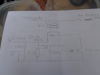
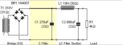
Thanks for the cap multiplier suggestion. I've attached the PSUD model of the power supply. There was a big inductor missing from the LTSpice sim of the soft start. The transformer is actually 310V-0V-310V.One option would be to change that circuit into a sort of cap multiplier by returning C2 to ground. OK the voltage would start rising immediately, but it could be made to take a loooong time... Just a thought.
Attachments
No splats, that with a HT of 450v loaded and over 1100uof capacitance. Very slight bump on SW off. I've attached the circuit I used,this gives a delay of 8-10 seconds, which I found a bit too short. 15 seconds would be better with possibly the same circuit replicated with a longer delay of 20-25 seconds. By experimenting you could have a stepped,soft delay.
I looked at your schematic and thought a slight alteration may work, use an RC to gradually bring the gate of the mosfet up. I used this site - RC time constant / voltage calcultor to find the correct values for R & C with a bit of experimentation. See also - Soft-Start Circuit For Power Amps you may have seen this but Rod deals with the subject in depth.
Thanks. I'll take a close look tomorrow.
Member
Joined 2009
Paid Member
Capacitor multiplier for soft start?
Thanks everyone for your input. I'm looking to move things around so I can fit in a TV damper diode or a pair as rectifiers. I could probably still get 400V out of a pair of 6CG3s.
A couple of relays to switch in a couple of resistors could still be the easiest option.Say one relay to switch in 2.2k, another to switch in a second 2.2k in parallel followed by a third to bypass them both. Soft-Start Circuit For Power Amps (Inrush Current Limiter) was very useful.
Mention of a capacitor multiplier got me thinking. I haven't seen them used in high voltage tube amp supplies. But if I can make 800uF look like 8F that should provide a very slow rise time. Rod Elliot has a good page on the topic, A Simple Capacitance Multiplier Power Supply For Class-A Amplifiers, but his is only low voltage. I tried simulating his circuit with 400V and some component value changes (but no attention paid to the voltage ratings of the transistors) and a rise time of 30s is easily doable.
Here is an idea:
Use a single TV damper diode in series after the SS rectification. I would suggest the venerable 6AU4-GT or 6AU4-GTA since it has low internal resistance and comes up VERY slow.
Heater warm-up time is a whopping 11 seconds on the specs sheet... But I have some examples (Sylvania) that come up in around 8 seconds. I have a few RCA's that take as long as 14 seconds too.
My experience with this diode is that it is VERY tough. use a separate heater transformer for it. Nothing expensive though. Just make sure it can handle the Heater current requirement of 1.8A
The plate can dissipate 6 Watts. I know you will love these.")
Be aware: These are still quite cheap. Don't buy too many (like I did) since you will probably never kill one then will get stuck with a few "lifetimes" worth of supplies. I personally love the most ugly "coin base" variety with the "curly" heaters and clear top. Don't pay too much or buy too many. Serious.
Sure, you could do the same with a single 6CG3 but I do not know if they come up quite as slow.
Best regards
Ian
Use a single TV damper diode in series after the SS rectification. I would suggest the venerable 6AU4-GT or 6AU4-GTA since it has low internal resistance and comes up VERY slow.
Heater warm-up time is a whopping 11 seconds on the specs sheet... But I have some examples (Sylvania) that come up in around 8 seconds. I have a few RCA's that take as long as 14 seconds too.
My experience with this diode is that it is VERY tough. use a separate heater transformer for it. Nothing expensive though. Just make sure it can handle the Heater current requirement of 1.8A
The plate can dissipate 6 Watts. I know you will love these.
Be aware: These are still quite cheap. Don't buy too many (like I did) since you will probably never kill one then will get stuck with a few "lifetimes" worth of supplies. I personally love the most ugly "coin base" variety with the "curly" heaters and clear top. Don't pay too much or buy too many. Serious.
Sure, you could do the same with a single 6CG3 but I do not know if they come up quite as slow.
Best regards
Ian
Last edited:
Final compromise
While I would have preferred a damper diode or tube rectified supply I really wanted to avoid a lot of work. Particularly cutting a new hole(s) in the chassis top to take the new tube(s). I loathe metalwork and get all my new builds laser cut.
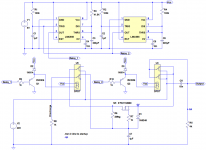
So, I’m using a delay followed by a capacitor multiplier to give a slow rise of the HT followed by a relay to bypass the capacitor multiplier.
Schematic and output below. The transistors between the 555s and the relays are not necessary but the LTSpice simulation won’t work without them.
Hopefully the negative spike in the output when the second relay bypasses the capacitor multiplier won’t be audible.
I’ll design a PCB for it that will replace the simple delay that I installed a year ago.
While I would have preferred a damper diode or tube rectified supply I really wanted to avoid a lot of work. Particularly cutting a new hole(s) in the chassis top to take the new tube(s). I loathe metalwork and get all my new builds laser cut.
So, I’m using a delay followed by a capacitor multiplier to give a slow rise of the HT followed by a relay to bypass the capacitor multiplier.
Schematic and output below. The transistors between the 555s and the relays are not necessary but the LTSpice simulation won’t work without them.
Hopefully the negative spike in the output when the second relay bypasses the capacitor multiplier won’t be audible.
I’ll design a PCB for it that will replace the simple delay that I installed a year ago.
Attachments
Minor updated to avoid switchover transient
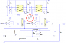
I added a resistor and capacitor (in red outline in the schematic below) to delay the disabling of the first relay.
This eliminates the spike in the previous plot when the second relay bypasses the capacitor multiplier at t=24s caused by the switchover time of the relays (simulation output below). Now the 2 relays overlap very slightly.
Attachments
Capacitor multiplier not giving expected soft start
My requirement is for a sufficiently slow rise in the HT that I don't get uncontrolled movement of the attached driver cone when the HT is applied. Tube rectification is difficult due to lack of space on and in the amp chassis.
I've finally tested my capacitor multiplier soft start and I'm not getting the soft start I was expecting.
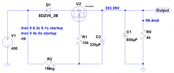
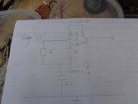
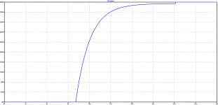
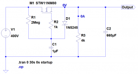
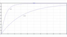
Schematic of just the cap multiplier is shown below with simulated output for R1 values of 2M and 10M.
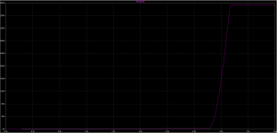
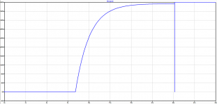
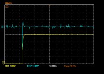
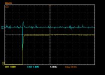
Also shown is the actual measured output for R1 values of 2M and 4M. Yellow trace is the HT and the blue trace is the amp output.
The cap multiplier doesn't appear to be giving me a slower rise time than the power supply without the cap multiplier. Increasing R1 doesn't slow the rise time.
The other schematic shown below didn't give me a slower rise time either even when I increased R2 to 10M despite the simulating saying otherwise.
What am I missing?
My requirement is for a sufficiently slow rise in the HT that I don't get uncontrolled movement of the attached driver cone when the HT is applied. Tube rectification is difficult due to lack of space on and in the amp chassis.
I've finally tested my capacitor multiplier soft start and I'm not getting the soft start I was expecting.
Schematic of just the cap multiplier is shown below with simulated output for R1 values of 2M and 10M.
Also shown is the actual measured output for R1 values of 2M and 4M. Yellow trace is the HT and the blue trace is the amp output.
The cap multiplier doesn't appear to be giving me a slower rise time than the power supply without the cap multiplier. Increasing R1 doesn't slow the rise time.
The other schematic shown below didn't give me a slower rise time either even when I increased R2 to 10M despite the simulating saying otherwise.
What am I missing?
Attachments

- Home
- Amplifiers
- Tubes / Valves
- Really soft HT start for DHT amp