I don't know if any of you chaps have heard of these guys, but I just took a punt on buying their PreAmp kit:
Classique – Phono Valve Preamp Amplifier With Passive RIAA Using 12AX7 / 12AU7 – DIY Kit – Caledonian Audio
Whilst Caledonian stuff gets great reviews, I don't have quite the same space as the standard enclosure needs, as you can see in the picture below (Top LH shelf is the deck, the highest shelf on the right is for my phono stage):

However, as this comes as a kit (without the enclosure) I figured I could look at making a custom enclosure so I dropped them an email. The owner came back to me and has been really helpful. After a number of emails back and forth, trying to find a way to fit all the components into the space, I came to the conclusion that there were two two options, both with issues:
1. Two Housings.
Separate the PSU PCB and Transformers (which are lovely, but big bu99ers), from the Amp PCB and valves and join the two with cables. However, I have some safety concerns around having a cable carrying HT DC and felt it will be neater if everything is in one case. So we discussed whether a single transformer could work, but I liked the purity of the CA design in using 2 transformers.
2. Use smaller transformers.
So, what about smaller transformers? After all, we are only driving three small tubes. To stay with the CA separate power supply design, and perhaps mitigate the chances of hum even more, use two toroidal transformers? And to minimise space, could the heater transformer be smaller too?
Perhaps a compact toroidal for the HT Anode supply, such as this:
240V/6.3V toroid power transformer – Amp Maker: Guitar amp kits and parts
Then a miniature toroidal for the heater supply, such as this:
60032 | Nuvotem Talema 115V ac, 230V ac, 2 x 12V ac Toroidal Transformer, 7VA 2 Output | RS Components
In the end, we decided that option 1 (two housings) could work if the PSU PCB was housed within the PreAmp housing.
I.E. A separate enclosure, housing the two transformers, building the enclosure from mild steel sheet with a central steel bulkhead, separating the two transformers. Then in the Preamp enclosure, I house both the preamp pcb and psu pcb, again with bulkhead between them. Then, all that is required between the two, is a 5-way cable linking the enclosures, comprising 2x twisted pairs (one for heaters and one for HT), each pair within its own shielded outer (e.g. shielded heat shrink), with shielding only grounded at the transformer enclosure, and a high-quality / low resistance grounding strap between the two enclosures.
However, space is still going to be tight in my application.
Height wise, the distance between the preamp shelf and the overlappling turntable shelf above, means I have 67mm of available height. Taking into account the 52mm for the 220uf 400v capacitor including the power supply board, that allows 15mm for the PCB mount, case and feet. Case top and bottom will total 3mm, feet about 5mm and if I use 5mm PCB mounts, I will have a couple of mm clearance. Tight as a gnat's chuff!
As far as width and depth are concerned, here are 1:1 scale cardboard representations of the 2x PCBs laid onto the original template I sent to the stonemasons who made the slate shelving for me:

As it happens, I was planning to copy the shape of the black slate shelf when creating the preamp case. As you can see; there is just enough room for the outer case (and a bulkhead between the PCBs to ensure EMF separation), with an area behind the amp pcb to site the input/output signal sockets and ground connection. There is also an area next to the power pcb, where I can site the power connections. Currently, all connections are hidden inside the shelving (power and signal in separate channels) so I should be able to also do this with the preamp.
So, I should be able to end up with a discretly powered Valve Preamp that is exactly the same teardrop (ish) shape as the slate shelf, and not a cable in sight!
Once everything arrives and I get started, I will Blog here about my build experience and the results
B
Classique – Phono Valve Preamp Amplifier With Passive RIAA Using 12AX7 / 12AU7 – DIY Kit – Caledonian Audio
Whilst Caledonian stuff gets great reviews, I don't have quite the same space as the standard enclosure needs, as you can see in the picture below (Top LH shelf is the deck, the highest shelf on the right is for my phono stage):
However, as this comes as a kit (without the enclosure) I figured I could look at making a custom enclosure so I dropped them an email. The owner came back to me and has been really helpful. After a number of emails back and forth, trying to find a way to fit all the components into the space, I came to the conclusion that there were two two options, both with issues:
1. Two Housings.
Separate the PSU PCB and Transformers (which are lovely, but big bu99ers), from the Amp PCB and valves and join the two with cables. However, I have some safety concerns around having a cable carrying HT DC and felt it will be neater if everything is in one case. So we discussed whether a single transformer could work, but I liked the purity of the CA design in using 2 transformers.
2. Use smaller transformers.
So, what about smaller transformers? After all, we are only driving three small tubes. To stay with the CA separate power supply design, and perhaps mitigate the chances of hum even more, use two toroidal transformers? And to minimise space, could the heater transformer be smaller too?
Perhaps a compact toroidal for the HT Anode supply, such as this:
240V/6.3V toroid power transformer – Amp Maker: Guitar amp kits and parts
Then a miniature toroidal for the heater supply, such as this:
60032 | Nuvotem Talema 115V ac, 230V ac, 2 x 12V ac Toroidal Transformer, 7VA 2 Output | RS Components
In the end, we decided that option 1 (two housings) could work if the PSU PCB was housed within the PreAmp housing.
I.E. A separate enclosure, housing the two transformers, building the enclosure from mild steel sheet with a central steel bulkhead, separating the two transformers. Then in the Preamp enclosure, I house both the preamp pcb and psu pcb, again with bulkhead between them. Then, all that is required between the two, is a 5-way cable linking the enclosures, comprising 2x twisted pairs (one for heaters and one for HT), each pair within its own shielded outer (e.g. shielded heat shrink), with shielding only grounded at the transformer enclosure, and a high-quality / low resistance grounding strap between the two enclosures.
However, space is still going to be tight in my application.
Height wise, the distance between the preamp shelf and the overlappling turntable shelf above, means I have 67mm of available height. Taking into account the 52mm for the 220uf 400v capacitor including the power supply board, that allows 15mm for the PCB mount, case and feet. Case top and bottom will total 3mm, feet about 5mm and if I use 5mm PCB mounts, I will have a couple of mm clearance. Tight as a gnat's chuff!
As far as width and depth are concerned, here are 1:1 scale cardboard representations of the 2x PCBs laid onto the original template I sent to the stonemasons who made the slate shelving for me:
As it happens, I was planning to copy the shape of the black slate shelf when creating the preamp case. As you can see; there is just enough room for the outer case (and a bulkhead between the PCBs to ensure EMF separation), with an area behind the amp pcb to site the input/output signal sockets and ground connection. There is also an area next to the power pcb, where I can site the power connections. Currently, all connections are hidden inside the shelving (power and signal in separate channels) so I should be able to also do this with the preamp.
So, I should be able to end up with a discretly powered Valve Preamp that is exactly the same teardrop (ish) shape as the slate shelf, and not a cable in sight!
Once everything arrives and I get started, I will Blog here about my build experience and the results
B
Last edited:
Caledonia Audio ?--- first time I have heard of them and I live in Scotland ,Edinburgh it seems , I hope its better than the "Scottish " ( imported works ) Kartel watch I bought in St.Andrews which has the poor quality silver plate flaking off the rear due to skin acidity and they had the cheek to email me two weeks ago asking for a recommendation but their reply email address doesn't exist according to the MS server.
Cheers Chaps!
I cannot take too much praise for the shelving; I simply created tempates for my local stonemason to create them.Then, I fabricated some angle brackets to mount them, with channels hiding and separating power from signal paths. My current plan is to build a separate Power Supply unit from the amp.
I will update futher as things progress.
B
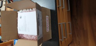
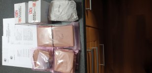
Well, the kit has arrived!
The CA Team contacted me to say the kit was being packed and ready to go. Then I got updates from the overnight delivery courier, from collection, to my door.
Nicely packed and labelled.
No instructions are included but there is a really comprehensive and well written 50 page build manual here: HERE
Not that I am impatient but I had already printed off and read the manual by the time I finished dinner. Now to unpack and check everthing is in order.
Cheers,
Ian
Attachments
 ...like their approach, curious to hear about the result!
Doh! Why didn't I think of that!
To Be honest, I rather prefer a good bottle of Craft Gin, but they don't make Gin in Scotland as far as i know)")
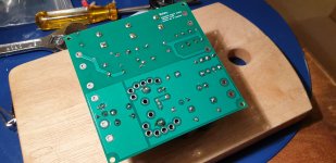
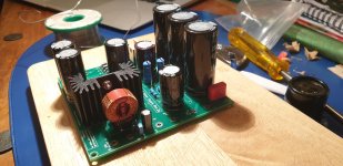
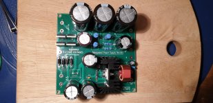
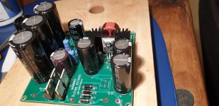
I have started putting together the kit. Power Supply PCB first.
This board combines both High-Voltage DC supply and the Low-Voltage DC heater supply, but separated on the PCB and supplied by individual transformers. PCB quality is very good indeed, as are the components. Transformers are provided by Primary Windings and the rest appear to be high-quality, low-tolerance RS-supplied items.
So, I set everything out, lined up my tools, fired up the soldering station and dropped a needle onto Pink Floyd's The Wall. Two hours later, this is the result (attached):
I have to admit finding to the process rather theraputic. I had a tough day at work today, up against a rather tight deadline to present to the board at the end of the day. However, focussing on checking component values (and re-learning the resistor colour band codes), methodically soldering them in, nipping off the excess legs and inspecting each joint before moving on, was very de-stressing. I am very much looking forward to the next stage!
Ian
To Be honest, I rather prefer a good bottle of Craft Gin, but they don't make Gin in Scotland as far as i know)
I have started putting together the kit. Power Supply PCB first.
This board combines both High-Voltage DC supply and the Low-Voltage DC heater supply, but separated on the PCB and supplied by individual transformers. PCB quality is very good indeed, as are the components. Transformers are provided by Primary Windings and the rest appear to be high-quality, low-tolerance RS-supplied items.
So, I set everything out, lined up my tools, fired up the soldering station and dropped a needle onto Pink Floyd's The Wall. Two hours later, this is the result (attached):
I have to admit finding to the process rather theraputic. I had a tough day at work today, up against a rather tight deadline to present to the board at the end of the day. However, focussing on checking component values (and re-learning the resistor colour band codes), methodically soldering them in, nipping off the excess legs and inspecting each joint before moving on, was very de-stressing. I am very much looking forward to the next stage!
Ian
Attachments
Boggie UK,
I'm interested in that Denon box - can you provide a model so I can research it?
Cheers,
Sure. Here you go:
Denon DCD50 | CD Player | Richer Sounds
https://www.vinylengine.com/turntable_forum/download/file.php?id=98003&mode=view
Well, I managed to free up another evening and after around three hours, this is the result:


It is a two-sided PCB, that is laid out so that the valve sockets can be mounted on either side. Putting everything on the same side will save height of course, but then only the tops of the valves could be poked through the case.
Now the real challenge begins; fitting the assembled PCBs and two hefty transformers into a custom case that will squeeze onto my PreAmp shelf....
Ian
Well, I managed to free up another evening and after around three hours, this is the result:
It is a two-sided PCB, that is laid out so that the valve sockets can be mounted on either side. Putting everything on the same side will save height of course, but then only the tops of the valves could be poked through the case.
Now the real challenge begins; fitting the assembled PCBs and two hefty transformers into a custom case that will squeeze onto my PreAmp shelf....
Ian
Neither can I!
However, it is going to be a little while yet, as building the case is turning out to be quite the challenge. When I originally designed the tiered shelving, I ony had to accomodate the modest-sized Pro-Ject Tube Box S. Now I am trying to fit in two PCBs, both being of similar size to the Tube Box S, plus 2 whopping great transformers:

I have been speaking to the Caledonian Audio team, who have been giving me excellent support (despite me taking their product rather off-piste), to get their thoughts / advice on what would or wouldn't work. They suggested that I should consider having the transformers in a separate box and to run the 2x power cables (HT and heater) between them. Not that this is a bad idea, and it would resolve my space issues, but I was keen to keep everything in one box.
So, after an evening creating models and trying different configurations, I think I can just about fit everything in, but only just. Cutting out a base plate, copied from the template I used to get the shelf made, I came up with this layout:
This project has given me a great excuse to buy some new tools; a slip roll to bend / curve sheet material and a folder to bend it. After en evening playing, I have got this far:
The biggest challenge now (quite literally) is how to install the 2x transformers in a vertical stack, ensuring it does not lead to EMF cross-talk, hum etc, and is not a big, unsightly box.
More thought required....
However, it is going to be a little while yet, as building the case is turning out to be quite the challenge. When I originally designed the tiered shelving, I ony had to accomodate the modest-sized Pro-Ject Tube Box S. Now I am trying to fit in two PCBs, both being of similar size to the Tube Box S, plus 2 whopping great transformers:
I have been speaking to the Caledonian Audio team, who have been giving me excellent support (despite me taking their product rather off-piste), to get their thoughts / advice on what would or wouldn't work. They suggested that I should consider having the transformers in a separate box and to run the 2x power cables (HT and heater) between them. Not that this is a bad idea, and it would resolve my space issues, but I was keen to keep everything in one box.
So, after an evening creating models and trying different configurations, I think I can just about fit everything in, but only just. Cutting out a base plate, copied from the template I used to get the shelf made, I came up with this layout:
An externally hosted image should be here but it was not working when we last tested it.
An externally hosted image should be here but it was not working when we last tested it.
An externally hosted image should be here but it was not working when we last tested it.
This project has given me a great excuse to buy some new tools; a slip roll to bend / curve sheet material and a folder to bend it. After en evening playing, I have got this far:
An externally hosted image should be here but it was not working when we last tested it.
The biggest challenge now (quite literally) is how to install the 2x transformers in a vertical stack, ensuring it does not lead to EMF cross-talk, hum etc, and is not a big, unsightly box.
More thought required....
I've had a slight rethink. The audio I/O area is going to be too small to get finger access to:
So I have moved the transformer tower location to the side and consolidated what little space I had on either side of the tower into the middle:

Another rethink on the transformer tower. Like all components in this kit, the transformers are of the highest-quality, but they are BIG transformers.. To reduce height I am going to experiment with fitting them at 90 degrees to each other and, to try and limit any EMF cross-talk between the two, I have welded in a bulkhead to separate them:

Another space issue came around the supplied 13A IEC socket. "Kettle Lead" plugs are rather chunky, and whilst pretty much the defacto standard for high-end amp power connections, are way over-rated for the requitrements of the CA PreAmp (the internal fuse is only rated at 500mA). So I started searching for an alternative. I found a 3-pin DIN power connector and chassis socket at RS Components. These are rated at 4A, so will be more than capable. The only issue is that the Caledonian Audio supplied IEC socket has a built in fuse, so I have had to buy a fuse holder as well (you can see both in the picture above) and made up a power cable to suit:

Time for trial wiring and shakedown (i.e. resolve any issues / identify any further mods needed) before I start on smartening up the enclosure; grind back welds, seam welding all the tacked panel joints, final fit of the lid and deciding on what finishes to apply.
Please note, that whilst I am going to great lengths to create a case that fits my rather challenging space, Caledonian Audio do supply a purpose-built and rather smart case, ready to fit all the supplied components into once the PCBs are built up! If I had use the CA case, I would have been enjoying my vinyl through end to end valve amplification by now... :-(
Ian
An externally hosted image should be here but it was not working when we last tested it.
So I have moved the transformer tower location to the side and consolidated what little space I had on either side of the tower into the middle:
An externally hosted image should be here but it was not working when we last tested it.
Another rethink on the transformer tower. Like all components in this kit, the transformers are of the highest-quality, but they are BIG transformers.. To reduce height I am going to experiment with fitting them at 90 degrees to each other and, to try and limit any EMF cross-talk between the two, I have welded in a bulkhead to separate them:
Another space issue came around the supplied 13A IEC socket. "Kettle Lead" plugs are rather chunky, and whilst pretty much the defacto standard for high-end amp power connections, are way over-rated for the requitrements of the CA PreAmp (the internal fuse is only rated at 500mA). So I started searching for an alternative. I found a 3-pin DIN power connector and chassis socket at RS Components. These are rated at 4A, so will be more than capable. The only issue is that the Caledonian Audio supplied IEC socket has a built in fuse, so I have had to buy a fuse holder as well (you can see both in the picture above) and made up a power cable to suit:
Time for trial wiring and shakedown (i.e. resolve any issues / identify any further mods needed) before I start on smartening up the enclosure; grind back welds, seam welding all the tacked panel joints, final fit of the lid and deciding on what finishes to apply.
Please note, that whilst I am going to great lengths to create a case that fits my rather challenging space, Caledonian Audio do supply a purpose-built and rather smart case, ready to fit all the supplied components into once the PCBs are built up! If I had use the CA case, I would have been enjoying my vinyl through end to end valve amplification by now... :-(
Ian
Hi Joe, I originally bought a ready-made cable as I planned to use the IEC method. I have bought a number of these cables. They are a high-quality, low-Bullsh*t cables at a really good price. The braiding is polyester and the pure copper cable itself is fully screened, with the shield only conected at the plug end.
The original cable came from Amazon Here and the connectors from RS Here
The original cable came from Amazon Here and the connectors from RS Here
So, trial fit and wireup complete:


After a gradual increase of input voltage using a variac, checking all the voltages on the boards at each step, until I finally had 355 DV Volts on the Amp PSU.

Time to fit the valves and light them up!

All seemed well so I hooked up the record deck and plugged the preamp into my power amp for a listen. Sound quality appears good so far, but I was experiencing some hum in both channels. The Caledonian Audio team have been really helpful in working with me on identifying the source.
As the hum decayed, rather than stopping instantly when cutting power AND by shorting the RCA inputs cleared the hum, we came to the conclusion that this was probably an input issue, rather than the amp itself. So I removed the deck and checked the ground connection. It was connected but I realised I had the interconnect the wrong way around. It is a Pro-Ject "Connect-It" cable, which has the shield only connected at one end. This connection is supposed to be made at the Amp end, but I had it on the deck. So, I switched it around and reconnected everything and retested.
The good news is that hum had gone from the RH channel. The bad news is that it remained in the LH speaker. However, another noted change is that the hum in the LH speaker now disappears instantly when I disconnect the preamp power, not decaying as I originally noted. To be fair, this may well have been the case previously, as I was only really listening to the RH speaker due to its close proximity to the preamp power source. I swapped the inputs around, to see if the hum followed, but it stayed in the LH speaker. So, it seems possible that I had 2 hum issues; the incorrectly connected interconnect causing an input/decaying hum in the both channels (now addressed) and a second internally generated hum in the LH channel.
The most likely cause is stray EMF from the transformers in my custom case. I have read reviews of the Caledonian Audio PreAmp and nobody mentions hum at all. As my LH In/Out RCAs and the wiring between them and the amp PSU are the closest to the transformer tower (only 10mm away and with a 1mm steel sheet between them), this seems to confirn the source. Time for another rethink.
I stripped out all the electronics and added more steel to double the thickness of the bulkhead that separates the transformers from the Amp PSU and (I suspect more importantly) the signal I/O section, by fabricating and welding in a sealed tunnel into the space). This means that there is now 2mm of steel between the transformers and any sensitive bits inside the case. I am also fabricating the rear cover, as this was not in place when I was testing the amp the other day, so the transformer tower was open at the rear where the interconnects are plugged in, again with the LH cables/connectors closest to the transformers.
I have also ordered a roll of MCF5 shielding strip. It is a Cobolt alloy, similar to Mu-Metal in composition, which promises 40dB attenuation in LF EMF with two layers applied. Once it arrives, I will line the inside of the transformer tower and rear cover before putting everything back together. I have also bought a roll of Faraday tape, which I will use to line the AMP PCB enclosure and the inside of the I/O section (mainly to prevent any RF interference). Lastly, I will use EMI Shielding heat shrink tubing to all the I/O signal wires and the AC supply wires, to and from the transformers.
If all of this does not resolve my issues I will go back to the drawing board, probably to build 2 enclosures; one for the Amp and the other to house the transformers. To be fair, this was the original suggestion by the Caledonian Audio team when I explained my space issues and the fact that I could not use their case to house the amp. I am absolutely sure that the two enclosure option (or indeed builing it into the Caledonian Audio case) will resolve the hum but I am keen to exhaust all "one box" options first....
An externally hosted image should be here but it was not working when we last tested it.
After a gradual increase of input voltage using a variac, checking all the voltages on the boards at each step, until I finally had 355 DV Volts on the Amp PSU.
Time to fit the valves and light them up!
All seemed well so I hooked up the record deck and plugged the preamp into my power amp for a listen. Sound quality appears good so far, but I was experiencing some hum in both channels. The Caledonian Audio team have been really helpful in working with me on identifying the source.
As the hum decayed, rather than stopping instantly when cutting power AND by shorting the RCA inputs cleared the hum, we came to the conclusion that this was probably an input issue, rather than the amp itself. So I removed the deck and checked the ground connection. It was connected but I realised I had the interconnect the wrong way around. It is a Pro-Ject "Connect-It" cable, which has the shield only connected at one end. This connection is supposed to be made at the Amp end, but I had it on the deck. So, I switched it around and reconnected everything and retested.
The good news is that hum had gone from the RH channel. The bad news is that it remained in the LH speaker. However, another noted change is that the hum in the LH speaker now disappears instantly when I disconnect the preamp power, not decaying as I originally noted. To be fair, this may well have been the case previously, as I was only really listening to the RH speaker due to its close proximity to the preamp power source. I swapped the inputs around, to see if the hum followed, but it stayed in the LH speaker. So, it seems possible that I had 2 hum issues; the incorrectly connected interconnect causing an input/decaying hum in the both channels (now addressed) and a second internally generated hum in the LH channel.
The most likely cause is stray EMF from the transformers in my custom case. I have read reviews of the Caledonian Audio PreAmp and nobody mentions hum at all. As my LH In/Out RCAs and the wiring between them and the amp PSU are the closest to the transformer tower (only 10mm away and with a 1mm steel sheet between them), this seems to confirn the source. Time for another rethink.
I stripped out all the electronics and added more steel to double the thickness of the bulkhead that separates the transformers from the Amp PSU and (I suspect more importantly) the signal I/O section, by fabricating and welding in a sealed tunnel into the space). This means that there is now 2mm of steel between the transformers and any sensitive bits inside the case. I am also fabricating the rear cover, as this was not in place when I was testing the amp the other day, so the transformer tower was open at the rear where the interconnects are plugged in, again with the LH cables/connectors closest to the transformers.
I have also ordered a roll of MCF5 shielding strip. It is a Cobolt alloy, similar to Mu-Metal in composition, which promises 40dB attenuation in LF EMF with two layers applied. Once it arrives, I will line the inside of the transformer tower and rear cover before putting everything back together. I have also bought a roll of Faraday tape, which I will use to line the AMP PCB enclosure and the inside of the I/O section (mainly to prevent any RF interference). Lastly, I will use EMI Shielding heat shrink tubing to all the I/O signal wires and the AC supply wires, to and from the transformers.
If all of this does not resolve my issues I will go back to the drawing board, probably to build 2 enclosures; one for the Amp and the other to house the transformers. To be fair, this was the original suggestion by the Caledonian Audio team when I explained my space issues and the fact that I could not use their case to house the amp. I am absolutely sure that the two enclosure option (or indeed builing it into the Caledonian Audio case) will resolve the hum but I am keen to exhaust all "one box" options first....
"...If all of this does not resolve my issues I will go back to the drawing board, probably to build 2 enclosures; one for the Amp and the other to house the transformers. To be fair, this was the original suggestion by the Caledonian Audio team when I explained my space issues and the fact that I could not use their case to house the amp. I am absolutely sure that the two enclosure option (or indeed builing it into the Caledonian Audio case) will resolve the hum but I am keen to exhaust all "one box" options first...."
That exactly what my experience was when I was building my headphone amp. Whatever measures I took, the hum remained (in the end almost not noticeable but.... ).
Then I decided to completely separate the power part from the amplifier part both in their own cabinet.
Result: Got completely rid of hum even with volume control to almost maximum.
The only thing left is to connect both parts decently together. That's why I asked you where you purchased those nice looking cables . Thanks for that info !
Joe.
That exactly what my experience was when I was building my headphone amp. Whatever measures I took, the hum remained (in the end almost not noticeable but.... ).
Then I decided to completely separate the power part from the amplifier part both in their own cabinet.
Result: Got completely rid of hum even with volume control to almost maximum.
The only thing left is to connect both parts decently together. That's why I asked you where you purchased those nice looking cables
. Thanks for that info !Joe.
Quick update:
The MCF foil arrived from Germany. Dangerous stuff! At only 0.06mm thick but very stiff, it has edges like razor blades. To add yet more peril, it is also rather springy, so coiling it up in order to help position and fix it to double-sided tape inside the transformer housing, only to have to spring open without warning, has resulted in us running out of plasters and me with numerous cuts. However, it is now in and two layers, so in theory I should have a 40dB attenuation of any EMI hum. Plus I have added a couple of layers of aluminium shielding tape on top, for good measure. I am hopeful that all this, with the addition of another layer of steel around the transformers and I/O tunnel, that hum will have been more or less eliminated.

I have decided to focus on finishing the case for now, as even if the shielding does not cure the hum and I have to remotely locate the transformers, I will keep this case for the amp and psu PCBs. So, I have spent the last few days making new rear and top covers, seam welding and cleaning up all the joints, removing surface imperfections and applying etch primer and filler coats in prep for top coat.
Then the top coats of paint.

And trial assembly.

I ill leave the paint a couple of days, then flat and polish. I especially want to get a black-mirror finish on the top plate to reflect the valves.
I appreciate all this welding and painting is a but dull, but I will soon get to the interesting bit of wiring it up and testing. I have a few sets of ECC83 valves (Vintage Mullards, JJs, Golden Lions etc) to test and will let you all know how the Caledonian Classique Pre-Amp sounds. I can't wait!
Cheers,
Ian
The MCF foil arrived from Germany. Dangerous stuff! At only 0.06mm thick but very stiff, it has edges like razor blades. To add yet more peril, it is also rather springy, so coiling it up in order to help position and fix it to double-sided tape inside the transformer housing, only to have to spring open without warning, has resulted in us running out of plasters and me with numerous cuts. However, it is now in and two layers, so in theory I should have a 40dB attenuation of any EMI hum. Plus I have added a couple of layers of aluminium shielding tape on top, for good measure. I am hopeful that all this, with the addition of another layer of steel around the transformers and I/O tunnel, that hum will have been more or less eliminated.
I have decided to focus on finishing the case for now, as even if the shielding does not cure the hum and I have to remotely locate the transformers, I will keep this case for the amp and psu PCBs. So, I have spent the last few days making new rear and top covers, seam welding and cleaning up all the joints, removing surface imperfections and applying etch primer and filler coats in prep for top coat.
An externally hosted image should be here but it was not working when we last tested it.
Then the top coats of paint.
And trial assembly.
I ill leave the paint a couple of days, then flat and polish. I especially want to get a black-mirror finish on the top plate to reflect the valves.
I appreciate all this welding and painting is a but dull, but I will soon get to the interesting bit of wiring it up and testing. I have a few sets of ECC83 valves (Vintage Mullards, JJs, Golden Lions etc) to test and will let you all know how the Caledonian Classique Pre-Amp sounds. I can't wait!
Cheers,
Ian
A few more pictures of the final fit-out. I still have to fit the transformers and make the valve holes in the new top cover, the positioning of which are pivotal as I only have 1mm difference between the OD of the valve mounts and the size of my hole punch.....


All AC lines are twisted together and encased in shielded heat-shrink, grounded at the safety earth at the point where the incoming power connection is grounded. The DC power feeds into the amp enclosure are also twisted and encased within shielded heatshring (also grounded at the safety earth), although with DC this is not really needed. The transformer tower is separated by 2x 1mm cold-rolled mild steel sheet from any sensitive componentry and the tower is internally lined with 2x MCF foil laters and aluminium tape.
An externally hosted image should be here but it was not working when we last tested it.
All AC lines are twisted together and encased in shielded heat-shrink, grounded at the safety earth at the point where the incoming power connection is grounded. The DC power feeds into the amp enclosure are also twisted and encased within shielded heatshring (also grounded at the safety earth), although with DC this is not really needed. The transformer tower is separated by 2x 1mm cold-rolled mild steel sheet from any sensitive componentry and the tower is internally lined with 2x MCF foil laters and aluminium tape.
- Home
- Amplifiers
- Tubes / Valves
- Caledonian Audio - Classique Valve Phono Preamp