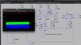
looks to me you used air core traffo, can ferrite be used? have you tried?
the plate choke, is that 4.7millihenry or 4.7 microhenry?
my idea is adaptation of ss circuits replacing the Mosfets with power tubes, driving tubes would be easier since the electrode capacitances are much lower with power tubes...
For pure switching perhaps a Thyratron would be better? Like a triode it can be controlled and supports higher current but doesn’t support linear amplification.
This was more aligned with my thoughts:
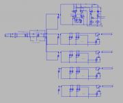
Using a an APFC to give 390V DC, then using flybacks to provide step up to provide a +320 -200 supply for the front end (60mA), and a supply 320V for each of the phases on each channel.
It would simplify I suspect that the channels become a push-pull switching system, with a shared oscillator (actually the the oscillator could be shared across all).
Heaters would be run by a separate flyback off off the same APFC.
Last edited:
looks to me you used air core traffo, can ferrite be used? have you tried?
the plate choke, is that 4.7millihenry or 4.7 microhenry?
That would depend on the frequency and peak current. I suspect uH.
Also those large power supply tubes would need shielding (I assume you're running at 75-300KHz).
Last edited:
So typically a triangle wave is used for ease of approximation, a flat top also gives an easy duty cycle limit for when the system is allow to be on out of the cycle.
There's a number of different strategies with SMPS - I'm going to go with a fixed ON trigger driven by the start of the duty cycle. Then be flexible with when the pulse comes to an end due to any of the following:
* voltage achieved
* current sense voltage hit limit
* duty cycle complete
The fixed method makes it easier to filter although using square wave allows noise to be sent far further up it adds noise at 0 but not really an issue. The slew rate of a valve is good enough for dI/dt to be relatively high but most of the valves then can't cope with high current unless they're big assed kV and up. Also a triangle is easier to approximate with an RC network and you get the DC for free..
Still working on this..
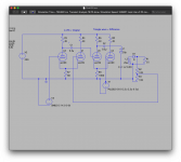
So.
1. Compare the scaled final voltage vs the input signal - the result is an output of "Vdifference". Basically it says if the output needs more power.
2. Compare the Vdifference to the oscillator triangle wave. Basically to say how much more for a pulse.
3. A triode schmitt trigger could then be added to check the current and cut the output from 2 should the current sense resistor get to it's maximum value.
This means if the output drops due to overload or short that the system self limits it's power output.
A trigger could also be used on the output to short and then cut the power completely.. or simply short the input and blow the fuse.
There's a lag in the pulse and could with the magnetic flux overshoot in terms of voltage, so it could be possible to make a compensation network to shape the pulse and give it a finer feedback adjustment so lessen the energy issued on each pulse on overshoot.
Probably and easier way todo this but for now working out voltage comparison with triodes is enough brain ache.
There's a number of different strategies with SMPS - I'm going to go with a fixed ON trigger driven by the start of the duty cycle. Then be flexible with when the pulse comes to an end due to any of the following:
* voltage achieved
* current sense voltage hit limit
* duty cycle complete
The fixed method makes it easier to filter although using square wave allows noise to be sent far further up it adds noise at 0 but not really an issue. The slew rate of a valve is good enough for dI/dt to be relatively high but most of the valves then can't cope with high current unless they're big assed kV and up. Also a triangle is easier to approximate with an RC network and you get the DC for free..
Still working on this..

So.
1. Compare the scaled final voltage vs the input signal - the result is an output of "Vdifference". Basically it says if the output needs more power.
2. Compare the Vdifference to the oscillator triangle wave. Basically to say how much more for a pulse.
3. A triode schmitt trigger could then be added to check the current and cut the output from 2 should the current sense resistor get to it's maximum value.
This means if the output drops due to overload or short that the system self limits it's power output.
A trigger could also be used on the output to short and then cut the power completely.. or simply short the input and blow the fuse.
There's a lag in the pulse and could with the magnetic flux overshoot in terms of voltage, so it could be possible to make a compensation network to shape the pulse and give it a finer feedback adjustment so lessen the energy issued on each pulse on overshoot.
Probably and easier way todo this but for now working out voltage comparison with triodes is enough brain ache.
Last edited:
So getting a simple DC level is straight forward. Having some 'fun' with a signal after having to resort to push pull. Decidedly DC offset on the secondary side..
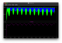
Top panel is the push pull wave form in the output tube primaries. Bottom is the voltage for the load..
However the FFT isn't too bad considering (no filters)
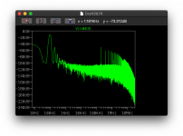
A little more sim time:
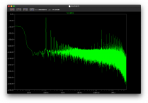
Will need to go through an check.. seems too good to be true..
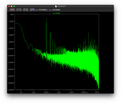
Longer - seems noisy but not overly..

Top panel is the push pull wave form in the output tube primaries. Bottom is the voltage for the load..
However the FFT isn't too bad considering

A little more sim time:

Will need to go through an check.. seems too good to be true..

Longer - seems noisy but not overly..

Last edited:
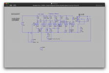
Will need to go through an check.. seems too good to be true..
View attachment 946414
A few things jump out at me after a quick look. Seems to me like two independent outputs, for PP one of the primaries is back to front, and there seem to be two independent transformers, not one push pull, and the load looks odd, no smoothing cap?
Interesting stuff.
A few things jump out at me after a quick look. Seems to me like two independent outputs, for PP one of the primaries is back to front, and there seem to be two independent transformers, not one push pull, and the load looks odd, no smoothing cap?
Interesting stuff.
The feedback keeps that in check. The three way shared cathode is a comparator with has two phase output - probably not the best way.
I was thinking this morning, given the triangle wave gives additional Fourier noise spread, I was thinking this could be adjusted so that the system uses square waves and current sense allowing deflection style higher plate voltage but current chopping to prevent overheating. Again the schmitt trigger (two triodes/npn) comes to mind - the triangle wave current sits at 100% duty cycle territory but this is not a problem because it's scaled by the required voltage difference - so switched yes, perhaps not completely class-D. An intermediate step if you will.
The adjustment I'm thinking of sees essentially this becoming a rail-to-rail swing, but uses the crossing points as trigger/disable given the number of inputs. It would possibly mean I can use 390V straight off the DC link rather than the 200V currently. I need to have a think and plan out the steps.
Last edited:
Interesting site on Thyratrons: Thyratrons | Threeneuron's Pile o'Poo that shows their ionisation and deionisation response times and current capabilities which may prove a little too slow for this.
Interesting idea....I must say I fond the idea of a switching valve amp intriguing, but I have no idea why!
but then I'm still toying with the idea of a valve 1V/Octave VCO, with micro power valves...
Many years ago I tried this with major thermal and noise issues. I then ventured into a mix of tube and solid state tech with similar issues.
I did successfully build a VCO that used a tube CCS and reset switch with a capacitor to make a typical sawtooth VCO. I led a Teensy board control the reset timing and the CCS current. That worked reasonably well, but I decided that I would let the valves / tubes do their job where they best influence the sound. I have a tube VCA performing better than I expected, but my vacuum tube Moog style ladder filter still needs work.
A square / sawtooth or other typical synth waveform will sound the same regardless of what made it, so my 1/V/oct VCO's are now digital. So are the LFO's and ADSR's.
Quick play whilst the food is cooking for lunch.
Here is my scmitt trigger running, it's set to 10V, so when the triangle rises above that it triggers the front of the square wave.
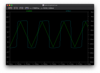
So this provides the maximum 'on' period, the hard stop as well as I'll make the output enable only during the top of the plateau. The back side of the wave is less important but I could make a secondary trigger to sense the downward threshold.
Next is to add two senses - the first will be the current sense, simply a 1V sense voltage that feeds a schmitt trigger that should then stop the square wave enable early.
Then the second is the voltage sense - essentially looking at the back end of the wave and asking 'is the voltage there yet' to stop the square wave enable.
Here is my scmitt trigger running, it's set to 10V, so when the triangle rises above that it triggers the front of the square wave.

So this provides the maximum 'on' period, the hard stop as well as I'll make the output enable only during the top of the plateau. The back side of the wave is less important but I could make a secondary trigger to sense the downward threshold.
Next is to add two senses - the first will be the current sense, simply a 1V sense voltage that feeds a schmitt trigger that should then stop the square wave enable early.
Then the second is the voltage sense - essentially looking at the back end of the wave and asking 'is the voltage there yet' to stop the square wave enable.
So the LT1249 is an Active Power Factor Corrector IC that's capable of 1500W. I tried running a tube on it, it works but not quite the same as running a beefy mosfet..
What is nice about this particular chip is that the internal switching speed is set at 100KHz rather than the normal slower 20-50Khz.
So this is likely to become core driver, then hang power supplies off for the direct-tube-OTL-switching-thingy, along with the heater supplies etc.
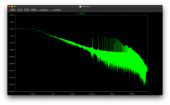
This is it hammering along at about 300W as the design in the data sheet.
It still has noise and ripple to cope with but it does a nice job of spreading the current over the mains sine wave however it's nicely outside of the audio spectrum compared to other chips.
What is nice about this particular chip is that the internal switching speed is set at 100KHz rather than the normal slower 20-50Khz.
So this is likely to become core driver, then hang power supplies off for the direct-tube-OTL-switching-thingy, along with the heater supplies etc.

This is it hammering along at about 300W as the design in the data sheet.
It still has noise and ripple to cope with but it does a nice job of spreading the current over the mains sine wave however it's nicely outside of the audio spectrum compared to other chips.
Many years ago I tried this with major thermal and noise issues. I then ventured into a mix of tube and solid state tech with similar issues.
I did successfully build a VCO that used a tube CCS and reset switch with a capacitor to make a typical sawtooth VCO. I led a Teensy board control the reset timing and the CCS current. That worked reasonably well, but I decided that I would let the valves / tubes do their job where they best influence the sound. I have a tube VCA performing better than I expected, but my vacuum tube Moog style ladder filter still needs work.
A square / sawtooth or other typical synth waveform will sound the same regardless of what made it, so my 1/V/oct VCO's are now digital. So are the LFO's and ADSR's.
Speaking from experience!
I havent any, so...I just had a crack pot idea.
I have enough DH pentodes with very low filament current and neons also, to make 25 oscillator and a small 25 key bed, and argh 25 key polyphony....
Or I could try and make a 1V/Octave and small keybed, maybe a sub osc. or multiple.
It's not something I want perfect, just something along the lines of a 555 organ, or 8038 organ which I am toying with....
As per SI convention, 4.7 mH stands for 4.7 millihenry. Microhenry would be µH.the plate choke, is that 4.7millihenry or 4.7 microhenry?
Best regards!
Looks to me like the best option for the pfc front end is, for now, stick with a boost ccm such as https://www.ti.com/lit/ds/slusbq5d/...https%3A%2F%2Fwww.ti.com%2Fproduct%2FUCC28180 then size the inductor for the load.
I’m then thinking simply of using:
* isolated regulated cuk configured as step down for heaters
* isolated regulated cuk configured as step up for B+/B- for fronend
* use a simple isolation then use a tube modulating output stage for each channel
All of the above will need careful filtering given the switching simply travelling on the dc link between sections, plus filtering on each of the outputs. It’s almost like the power is best done using B+/B- rails.
So I've been obsessing over SMPS recently, through all the normal boost, buck, cuk, half bridge, and full bridge.. along with resonant tanks etc.. Oddly enough step down SMPS is quite a challenge if you have a high switching rate - the power dissipation is not efficient if you're only wanting a few tens of watts.. so it's looking like this will be a lower speed switched affair with a step down transformer to take the 390V to the heater 12.6V but then put masses of LPF filtering and EMI filtering on the low voltage side to be both power efficient and cost efficient.
Now part of the research and modelling into half bridges for that power supply ended up in Class D. Which led my thoughts on waking at 0550 back to the problem of tube modulated power output stages
Looking through the patents for Class D tubes.. I noted a link to Gerald Stanley's 1996 white paper for the Crown Balanced Current Amplifier. Reading it I was going 'yep that matches my thinking based on the modelling in ltspice' .. it almost pulls together my thinking (the idea of pulling MarcelD's valve dac into drive the output stage for DSD which I've discussed before) into a single document... in the white paper he makes the point about PWM and class B push pull problem around the zero point and gaps in the signal causing harmonics and noise.. as we all know, but instead proposes the use of DSD-esque pulse density switching rather than pulse width.. a nice fit with DSD512 at 2.7Mhz from MarcelD's work...
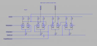
The paper gives a basic outline of a differential conversation stage into a DSD-esque output using a triangle wave. I doubt it's perfect but it consists of 4 comparitors.. which is basically where my tube-modulated SMPS was headed..
Two triodes per comparator, means four valves (I've put ecc99 here but this is likely to be more like running a higher frequency valve such as the 88 akin to MarcelD's valve dac).
Paper: https://www.google.com/url?sa=t&rct...original.pdf&usg=AOvVaw331XHXUkQh8o42iijw7-Li
If that link fails search for "Original_(1996)_White_Paper_on_Class-I_by_Gerald_Stanley_original.pdf" in your favourite inter webs search..
This has the feedback mechanism for correcting the issues typically found in switching, also the feedback allows for better impedance with OTL.
Basic Valve configuration - note I think this could work better in a different configuration as the first comparator simply makes it single ended rather than keeping it differential. It would be possible to make this fully differential right through but let's not run before we can walk. So I've started on an ltspice model for a direct transscription, WIP:
Naturally.. a filter before output - otherwise the poor OT will have saturation issues, or alternatively, go OTL which was my intent from the start with this idea..
Now it also occurred to me also.. that this could be mated to the ZOTL output stage - feeding the switching output as the switching and then an in phase audio input (the output from the power stage... through to help with any last impedance issues rather than relying on feedback alone.
Got to get on with the day job now but something to explore..
Now part of the research and modelling into half bridges for that power supply ended up in Class D. Which led my thoughts on waking at 0550 back to the problem of tube modulated power output stages
Looking through the patents for Class D tubes.. I noted a link to Gerald Stanley's 1996 white paper for the Crown Balanced Current Amplifier. Reading it I was going 'yep that matches my thinking based on the modelling in ltspice' .. it almost pulls together my thinking (the idea of pulling MarcelD's valve dac into drive the output stage for DSD which I've discussed before) into a single document... in the white paper he makes the point about PWM and class B push pull problem around the zero point and gaps in the signal causing harmonics and noise.. as we all know, but instead proposes the use of DSD-esque pulse density switching rather than pulse width.. a nice fit with DSD512 at 2.7Mhz from MarcelD's work...
The paper gives a basic outline of a differential conversation stage into a DSD-esque output using a triangle wave. I doubt it's perfect but it consists of 4 comparitors.. which is basically where my tube-modulated SMPS was headed..
Two triodes per comparator, means four valves (I've put ecc99 here but this is likely to be more like running a higher frequency valve such as the 88 akin to MarcelD's valve dac).
Paper: https://www.google.com/url?sa=t&rct...original.pdf&usg=AOvVaw331XHXUkQh8o42iijw7-Li
If that link fails search for "Original_(1996)_White_Paper_on_Class-I_by_Gerald_Stanley_original.pdf" in your favourite inter webs search..
This has the feedback mechanism for correcting the issues typically found in switching, also the feedback allows for better impedance with OTL.
Basic Valve configuration - note I think this could work better in a different configuration as the first comparator simply makes it single ended rather than keeping it differential. It would be possible to make this fully differential right through but let's not run before we can walk. So I've started on an ltspice model for a direct transscription, WIP:

Naturally.. a filter before output - otherwise the poor OT will have saturation issues, or alternatively, go OTL which was my intent from the start with this idea..
Now it also occurred to me also.. that this could be mated to the ZOTL output stage - feeding the switching output as the switching and then an in phase audio input (the output from the power stage... through to help with any last impedance issues rather than relying on feedback alone.
Got to get on with the day job now but something to explore..
- Home
- Amplifiers
- Tubes / Valves
- Tube modulated SMPS
