Hey everyone.
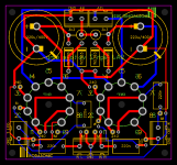
I've created a new PCB for an actively loaded triode voltage amp for the front end of my MA-1 power amp design for those who wanted to make it an integrated amp instead of using a separate preamp.
It has been built and tested, and works as expected.
It uses the larger 9 pin socket 21 odd mm instead of 18mm
I have a few left, and I will offer blanks, kits, and completes, but I'm also offering up the Gerber as an open source project.
Koda
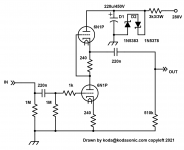
EDIT: Schematic error, see post #5
I've created a new PCB for an actively loaded triode voltage amp for the front end of my MA-1 power amp design for those who wanted to make it an integrated amp instead of using a separate preamp.
It has been built and tested, and works as expected.
It uses the larger 9 pin socket 21 odd mm instead of 18mm
I have a few left, and I will offer blanks, kits, and completes, but I'm also offering up the Gerber as an open source project.
Koda
EDIT: Schematic error, see post #5
Attachments
Last edited:
Instead of using a preamp on a power amp, this can be built into the power amp to make an integrated amp. (gain/volume front end).
It can also be used as a line stage if you change the 220n output cap to something larger. This will drive 100k easily, and probably drive 10k well enough.
It can also be used as a line stage if you change the 220n output cap to something larger. This will drive 100k easily, and probably drive 10k well enough.
Math isn't my strength, but I'd guess about 1k or so. Maybe PRR or GoatGuy (or one of so many smart people on this board) will be able to calculate it.
I call it High Z to differentiate it from the buffered version which can drive headphones, and because of the output caps only being 220n, you want to keep loading in the hundreds of k for good low frequency response (or make the cap 10uF and drive 10k)
Current is around 8mA.
EV is an uprated tube - I think of EV like "Heavy Duty" versions... It makes no difference in this circuit IMHO.
Last edited:
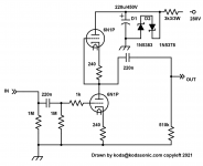
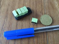
jean-paul asked about making room for 10uF film caps.
I use MKP20106J2EAC461625 by Kyet.
That way you can drive 10k with it. I won't be producing these but here is the artwork and a Gerber.
Koda
I use MKP20106J2EAC461625 by Kyet.
That way you can drive 10k with it. I won't be producing these but here is the artwork and a Gerber.
Koda
Attachments
Last edited:
Math isn't my strength, but I'd guess about 1k or so. Maybe PRR or GoatGuy (or one of so many smart people on this board) will be able to calculate it.
I call it High Z to differentiate it from the buffered version which can drive headphones, and because of the output caps only being 220n, you want to keep loading in the hundreds of k for good low frequency response (or make the cap 10uF and drive 10k)
Current is around 8mA.
EV is an uprated tube - I think of EV like "Heavy Duty" versions... It makes no difference in this circuit IMHO.
⋅-=≡ GoatGuy ✓ ≡=-⋅ chimes in … looks to about 2.7 kΩ, to me. I don't have time to really do the maths, but from the Svetlana data sheet, and all the usual hand-waving, ought to be about right.
Thanks! Psst ... it could use a muting circuit to avoid plops at power on...
I've never heard a "plop" at power on because the tubes aren't hot yet and the current comes up gradually. Unless you use a silly B+ delay that is.
⋅-=≡ GoatGuy ✓ ≡=-⋅ chimes in … looks to about 2.7 kΩ, to me. I don't have time to really do the maths, but from the Svetlana data sheet, and all the usual hand-waving, ought to be about right.
Thank you! I think my estimate was based on 6DJ8 now that I think of it
")
I've never heard a "plop" at power on because the tubes aren't hot yet and the current comes up gradually. Unless you use a silly B+ delay that is.
Read plops (normally the issue with way faster ramping up semiconductor stuff) as "slowly ramping up higher than allowable DC voltage charging the output capacitor that may damage any sensitive semiconductor device that may follow". A phenomenon that never can occur with a muted/shorted to GND output for let's say 15 to 30 seconds. It will make a marriage between semi and tube stuff a lasting good marriage. Simply good design practice without any drawback except a few Euro costs. When one chooses not to use this quite useful feature then the pads won't cost a thing extra. Just omit these parts and it suits both.
Grouping L and R outputs to one side would also be nice. Would be possible if the output caps would be turned 90 degrees and tubes also. You are a fast drawer, faster than I am anyway.
Last edited:
For that kind of "plop" tie 15V bidirectional TVS diodes across the outputs. Or use these instead. 2PCS 12VDC ADJUSTABLE OFF THEN ON DELAY TIME 0-60SECONDS 10 AMP RELAY BOARD X 2 | eBay
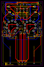
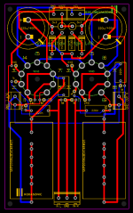
As requested extra pads for more cap sizes and thicker traces to those caps. I also cleaned up the redundant traced on the input. Now the board is almost as large as the buffered version though...
I like separate L and R sides. It can reduce crosstalk, and the wire to the connector is probably shielded instead of running across a PCB which isn't.
Also in case I never said, the 12V heater is not ground referenced on the PCB. This allows you to elevate the heater if you choose.
Koda
Attachments
Last edited:
It surprises me to have a tube device and then put non linear semi stuff in the signal path!?! Feels like cursing in the church and I am a semi guy Just like external muting solutions while it is perfectly possible to include the tiniest of tiny relay circuit with a handful of parts...fully standard in any quality semiconductor source device for decades..
Some might take this as negative but the comments are purely meant to add constructive suggestions for a virtual "versatile user friendly tube preamp that can be used in mixed environments" or?!
When using 45 degree angles please don't also use sharp 90 degree angles with PCB tracks.
A suggestion is the proven circuit in post #10:
https://www.diyaudio.com/forums/tubes-valves/335629-output-valve-preamp-voltage.html#post5737678
Just like external muting solutions while it is perfectly possible to include the tiniest of tiny relay circuit with a handful of parts...fully standard in any quality semiconductor source device for decades..Some might take this as negative but the comments are purely meant to add constructive suggestions for a virtual "versatile user friendly tube preamp that can be used in mixed environments" or?!
When using 45 degree angles please don't also use sharp 90 degree angles with PCB tracks.
A suggestion is the proven circuit in post #10:
https://www.diyaudio.com/forums/tubes-valves/335629-output-valve-preamp-voltage.html#post5737678
Attachments
Last edited:
This isn't meant to be a versatile user friendly preamp though. It's meant to drive a high Z first stage of a vacuum tube power amplifier with a Zin of 100k+ and it's offered for free (unless someone wants a board - I have 4 left).
The buffered version is the user friendly version. There are even 3 different input tube pinouts.
Why is there a problem using a safety diode when there are zener diodes in the PS filter? They are certainly in the signal path and more so since they are actually conducting. A TVS that isn't conducting is like a tiny (pico range) capacitor - no harm to audio IMHO. For the record - in 3 years of using circuits like these, I had one spike high enough to kill an opamp on an EQ It was an old 741, and I replaced it and it's pair with newer better parts. When I really need a muting circuit (Now that I discovered the TVS diode, I don't anymore), I use a time delay board like I linked.
Since there's an acre of space between those caps, I'll through that circuit on the board that you linked without values and run it from the 12V heater connection... If it blows up if someone referenced it to B+, don't get mad at me.
Also why not mix 45 and 90? What's the problem? Maybe I'll use arcs or just freehand on the next one LOL
and it's offered for free (unless someone wants a board - I have 4 left).The buffered version is the user friendly version. There are even 3 different input tube pinouts.
Why is there a problem using a safety diode when there are zener diodes in the PS filter? They are certainly in the signal path and more so since they are actually conducting. A TVS that isn't conducting is like a tiny (pico range) capacitor - no harm to audio IMHO. For the record - in 3 years of using circuits like these, I had one spike high enough to kill an opamp on an EQ It was an old 741, and I replaced it and it's pair with newer better parts. When I really need a muting circuit (Now that I discovered the TVS diode, I don't anymore), I use a time delay board like I linked.
Since there's an acre of space between those caps, I'll through that circuit on the board that you linked without values and run it from the 12V heater connection... If it blows up if someone referenced it to B+, don't get mad at me.
Also why not mix 45 and 90? What's the problem? Maybe I'll use arcs or just freehand on the next one LOL
Last edited:
- Home
- Amplifiers
- Tubes / Valves
- NEW PCB: Active loaded triode High Z 9AJ voltage amp.