You could say that the Zobel provides loading/damping at high frequencies only, but that's where it's needed in a properly designed amp. The output Zobel damps the speaker line with its unpredictable and always wrong termination. And the input Zobel damps/terminates the interconnecting cable, which is otherwise normally unterminated, thus a good antenna.
An input transformer gives you an additional luxury: both polarities of signal current can be carried together in a twisted pair plus shield back to the source end of the cable. Shield can be connected to chassis on both ends for best possible RFI immunity. If the source end is RCA's you can make a special wire with one side of twisted pair from RCA hot, one side and shield to RCA cold.
This way, no signal current is carried on the shield, so cannot be contaminated by it. In the conventional RCA to RCA connection, return currents are split equally between the two channels' returns, which are usually also the shields - a terrible mess. Coax cables only get their noise immunity by having equal and opposite inner and outer (shield) currents, so have very, very little in stereo unbalanced interconnections. It works, sort of, mostly, but is far from ideal. Not near good enough for instrumentation or critical cases like yours.
Folks sometimes try to approximate this correct layout by floating the input stage's signal ground by 5 or 10R and connecting it to the (floating) input jacks' "cold" connection. That's part way there, but separating shields and signal conductors is an important next step.
Ran on some, but it's an important topic, seldom discussed,
Chris
Last edited:
This is something I tried to achive here, and it helped a lot. Also raising the input stage signal GND by 10R from the rest of GND was a "secret trick" to killing hum.If the source end is RCA's you can make a special wire with one side of twisted pair from RCA hot, one side and shield to RCA cold.
This way, no signal current is carried on the shield, so cannot be contaminated by it.
Folks sometimes try to approximate this correct layout by floating the input stage's signal ground by 5 or 10R and connecting it to the (floating) input jacks' "cold" connection. That's part way there, but separating shields and signal conductors is an important next step.
Attachments
Thanks Chris!
There is another interesting situation, if anyone has ideas:
I've assembled about 5-6 of these PCB's and assembled 3 amps.
Some of the 22V Zener's seem to have failed. The part is: 1N5358BG
One, for example, shows a 5V drop instead of 22V.
The amp still works, but this results in a higher screen voltage.
Any idea's what could have caused them to fail?
When I got feedback on the PCB, one person pointed out:
Could that help?
There is another interesting situation, if anyone has ideas:
I've assembled about 5-6 of these PCB's and assembled 3 amps.
Some of the 22V Zener's seem to have failed. The part is: 1N5358BG
One, for example, shows a 5V drop instead of 22V.
The amp still works, but this results in a higher screen voltage.
Any idea's what could have caused them to fail?
When I got feedback on the PCB, one person pointed out:
You have a floating zener on the screen. I think you’ll want that to be ground referenced, no? As a minimum you’ll need a series resistor so the zener can regulate.
Could that help?
This is something I tried to achive here, and it helped a lot. Also raising the input stage signal GND by 10R from the rest of GND was a "secret trick" to killing hum.
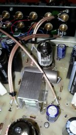
Sir, I bought a spool of similar (or the exact same?) military cabling a while ago and it seemed excellent quality. Then I finally used it in a very good device that was worthy of this cable
") Someone pointed out that it is military (I knew) airplane quality made of teflon, silver plated copper shielding etc. but also that its core is iron based. I did not believe I judged it wrong but I was astounded that it sticked to a magnet! I replaced it for normal copper cabling with less nice esthetical qualities but better sound as a result...
Someone pointed out that it is military (I knew) airplane quality made of teflon, silver plated copper shielding etc. but also that its core is iron based. I did not believe I judged it wrong but I was astounded that it sticked to a magnet! I replaced it for normal copper cabling with less nice esthetical qualities but better sound as a result...
Last edited:
As said, it sounded worse than standard pure copper cabling which makes using it a trivial issue. Whatever tubes are made of is not a variable, the cable is. A many only use the ears in the tube world this cable should be filtered out real fast when comparing with other cables...
In short: it only looks good.
In short: it only looks good.
Last edited:
1N5358BG
One, for example, shows a 5V drop instead of 22V.
The amp still works, but this results in a higher screen voltage.
Any idea's what could have caused them to fail?
When I got feedback on the PCB, one person pointed out:
Could that help?
I guess that the poster was trying to say that the Zeners are dropping out of conduction. They're rated to "Zener" or reverse conduct above about half a milliAmp, which seems conservative enough, but we're guessing here.
You can test this theory two ways: first, is the Zener diode actually damaged? Feeding a sample of the misbehaving ones from B+ though a suitable resistor (several hundred K Ohms and several Watts) to signal ground, will tell the tale.
Or, in circuit, you could add a bleeder resistor from G2 to signal ground to maintain a minimum diode reverse current. For an additional 1/2 milliAmp something like two 300K Ohm 2 Watt resistors in series for voltage rating should do.
Interesting question; please keep us posted on results.
All good fortune,
Chris
I have this occurrence on 2 separate boards.
On one of them, I replaced the Zener with a new one and it then dropped 22V as opposed to 5V. I didn't change anything else, so it does seem like it was faulty.
I didn't replace the Zeners on the other board, so I can try one of these experiments.
Searching for this issue, I did encounter this post over at AK:
In V1 of this circuit, there was a 2.2K resistor and not a Zener.
I'm considering swapping that in to prevent this from happening again
On one of them, I replaced the Zener with a new one and it then dropped 22V as opposed to 5V. I didn't change anything else, so it does seem like it was faulty.
I didn't replace the Zeners on the other board, so I can try one of these experiments.
Searching for this issue, I did encounter this post over at AK:
The zener is likely to fail with even a lint short in the tube and it will fail shorted and it will then cause the plate current which is already at the limit to rise. Besides you miss the advantage of filtering the G2 separately. The output tube has good power supply rejection due to high plate impedance but hanging the G2 off it ruins that. I wouldn't get much sleep worrying about that fragile zener sitting around all those volts.
In V1 of this circuit, there was a 2.2K resistor and not a Zener.
I'm considering swapping that in to prevent this from happening again
Connecting semiconductors to vacuum valves is "fraught with peril" of course, but folks do it (carefully) and things survive (mostly). But there's always a possibility - the valve's parts have comparatively long thermal time constants and gigantic dimensions - so we can't discount an actual semicon failure.
But most semicon failures are to short, and that's not what you're seeing. Also, a Zener is by nature pretty rugged, in the sense that its junction is meant to be reverse biased (an otherwise common semicon failure mode).
If my interpretation of the poster's theory holds, different individual Zeners may or may not break over in the existing circuit, so replacement wouldn't be conclusive. Curiouser and curiouser.
This question will prove important to folks who restore Golden Age gear, which often runs at very, very high voltages for modern (inferior!) valves, that could use some reduction in G2 voltage.
Thanks for your diligence, and all good fortune,
Chris
I guess that the poster was trying to say that the Zeners are dropping out of conduction. They're rated to "Zener" or reverse conduct above about half a milliAmp, which seems conservative enough, but we're guessing here.
You can test this theory two ways: first, is the Zener diode actually damaged? Feeding a sample of the misbehaving ones from B+ though a suitable resistor (several hundred K Ohms and several Watts) to signal ground, will tell the tale.
Or, in circuit, you could add a bleeder resistor from G2 to signal ground to maintain a minimum diode reverse current. For an additional 1/2 milliAmp something like two 300K Ohm 2 Watt resistors in series for voltage rating should do.
Interesting question; please keep us posted on results.
All good fortune,
Chris
I finally got to do this experiment. I didn't have large resistors on hand so used around 30K from g2 to ground. The Zener dropped around 3V vs. 2V beforehand, so I don't think this is a regulation issue.
This doesn't seem to be a common issue with this design (or folks haven't measured the amps after they have been in service for a while).
Trying to think of the reason for failure, perhaps it is in-rush current on power on, due to using SS diodes and largish capacitance.
I've seen Chinese fakes of things that a sensible person would never suspect. UF4007? They sell for pennies. Who would bother, and why? But they're out there.
Maybe a new batch from a different supplier would run better. Annoying, but cheap enough to try.
All good fortune,
Chris
Maybe a new batch from a different supplier would run better. Annoying, but cheap enough to try.
All good fortune,
Chris
I made multiple orders with this part, some from Mouser and some from Arrow.. both should be reputable.
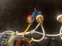
I replaced one of the faulty Zener's with a 2.2K resistor from the v1 schematic. The voltage drop was around 9.5V, so 4.3mA current draw on the screen.
I ran an FFT, 1khz at 1W output power comparing the channel with the Zener and the channel with the resistor and they measured basically the same.
With 310V B+, there is 305V on the plate and 300V on the screen with the 2.2K resistor; This should be good enough for my purposes.
Also, the voltage drop across the resistor during power-on increased very slowly; I assume as the heater was warming up it started to draw current.
I'm not sure how to interpret this with regards to the earlier hypothesis that the failure is caused by power on surge.
Circling back here, I had another situation of a failed Zener and failed LM317.
This was in a new amp, with a tube rectifier built exactly as the original schematic.
This time, I know the root cause, which is a bad EL84 tube. I had the exact pair of EL84's in the previous amp that had the similar failure and put them aside when it happened. I inserted them into the new amp intentionally to see if they would cause issues, and they did.
This aligns somewhat with Roger Modjeski's (R.I.P) criticism on the circuit over at AK:
That aside, I've been using the amp for a while with the bridge rectifier/resistor ground lift and it is very quiet connected to the noisy PC.
I've got a pair of unused Hammond 140UEX and was thinking of using them here.
Is this the correct wiring scheme?
-- Primaries connected to (isolated) input RCA.
-- Secondaries connected to 10K potentiometer input
-- Transformer case connected to chassis (i.e, not isolated)
-- Remove diode bridge/resistor so that ground is connected directly to chassis.
This was in a new amp, with a tube rectifier built exactly as the original schematic.
This time, I know the root cause, which is a bad EL84 tube. I had the exact pair of EL84's in the previous amp that had the similar failure and put them aside when it happened. I inserted them into the new amp intentionally to see if they would cause issues, and they did.
This aligns somewhat with Roger Modjeski's (R.I.P) criticism on the circuit over at AK:
There are a few things not to like about it. The zener is likely to fail with even a lint short in the tube and it will fail shorted and it will then cause the plate current which is already at the limit to rise. Besides you miss the advantage of filtering the G2 separately. The output tube has good power supply rejection due to high plate impedance but hanging the G2 off it ruins that. I wouldn't get much sleep worrying about that fragile zener sitting around all those volts.
...
The LM317 is at risk from a shorted tube. How about a fuse somewhere considering how many ways this circuit can run away?
That aside, I've been using the amp for a while with the bridge rectifier/resistor ground lift and it is very quiet connected to the noisy PC.
I've got a pair of unused Hammond 140UEX and was thinking of using them here.
Is this the correct wiring scheme?
-- Primaries connected to (isolated) input RCA.
-- Secondaries connected to 10K potentiometer input
-- Transformer case connected to chassis (i.e, not isolated)
-- Remove diode bridge/resistor so that ground is connected directly to chassis.
That's how I would do it. The input transformers can be expected to have such a high common-mode rejection that extra fiddling about interconnecting cables and shield currents can be ignored. Except for the #@%^& single-ended RCA cables and connectors, that's how professional gear is made, and it just works - no drama mama.
A correction to an earlier post by me: there is a good reason to include a 10R resistor across a double-double-diode isolator, and I was wrong to say otherwise. The resistor will stabilize the resting leakage voltage across the two-diode-each-way drops to near zero, so is important in high noise situations. Even a half Watt is fine here.
All good fortune,
Chris
- Home
- Amplifiers
- Tubes / Valves
- Noise pickup in tube amp, increases with volume