I'm in the final stretches of my RH84 based headphone amp.
With inputs shorted, the amp is dead silent across the entire range of the volume pot. B+ and heaters are regulated DC.
Connected to my PC workstation and DAC (Schiit Modius) there is a fair amount hashy noise as the volume pot is increased.
It seems source dependent as connected to an RPi based streamer, it is much quieter.
That said, the Modius connected to a SS amp (Neurochrome HP-2) is silent across the range, in both hi and lo gain settings.
The HP-2 has EMI filter on the input and I'm wondering if that could help in the tube amp as well? That or input transformers?
Any other suggestions?
Attachments
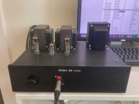

You know, 99% of you diy tubeamp guys build a flat chassis with the tubes on top- naked. I own 4 hammond organs and on the 3 H-100 models they put a steel cap over each tube engaging a spring steel grounded base ring, except the high watt output tubes and the power rectifier tubes. My dynaco ST-70 has a steel mesh cage over the top. My dynaco PAS2 amp has 2 steel boxes, a total enclosure and a smaller steel box around the 120 vac wires & power switch. But what did they know?
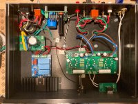
I see you have no heavy iron e core transformer to keep the interference from coming in the AC line. I see you have no steel box around the switcher supply as Peavey put around their switcher supply in the CS800s amp. What did they know?
I see no 33 pf disk caps across your input RCA jacks as Herald Electronics put across the inputs of their RA-88a disco mixer. What did they know?
It is a complete mystery why you have noise.
Last edited:
hi! thanks for your feedback although some humility wouldn't hurt.
as I mentioned the amp is dead silent, the noise is related to the specific source. it remains dead silent with other DAC's that are not connected to the PC.
Is this from signal to GND of the input jack or to chassis?
as I mentioned the amp is dead silent, the noise is related to the specific source. it remains dead silent with other DAC's that are not connected to the PC.
I am using a 220uF cap and Maida regulator which does a good job at providing a quiet B+. The choke should not necessary with it.I see you have no heavy iron e core transformer to keep the interference from coming in the AC line.
Which switcher supply? The heater is linear regulatedI see you have no steel box around the switcher supply as Peavey put around their switcher supply in the CS800s amp.
I see no 33 pf disk caps across your input RCA jacks as Herald Electronics put across the inputs of their RA-88a disco mixer. What did they know?
Is this from signal to GND of the input jack or to chassis?
The 33 pf caps are supposed to keep RF from getting in your steel box from the input jacks.
As originally designed by Herald Electronics, the RA-88a mixer connected the RF trap caps to the steel shell. I found they worked better if I isolated the RCA jack shells from the steel case, and connected the rings of the RCA jacks to the analog ground of the input. The 33 pf caps were right on the jacks. There was a hum dimension to the noise that was particularly annoying, caused in part by non-ideal grounding. I used rubber o-rings from the industrial supply to isolate the RCA jack rings from the case metal.
Other possible entries of RF noise to a steel box are the power entry, and the output jacks.
If you don't have a switcher supply, that won't be producing RF right inside your case. I do see on third look that you have EI iron core transformers outside your steel box.
Of course, your receiving tubes are right outside the steel box.
If you have a digital source, your input may contain noise that is below the filter capability of 33 pf disk caps. I had an early synthsizer that howled rather annoyingly into following mixers based on the frequency of the computer programs inside.
Best of fortune in the pursuit of quiet.
Last edited:
Headphone amps are more sensitive to noise. You may need to "lift" the signal ground from the chassis ground. I see there is no input coupling capacitor, your source may have some DC offset present. Also there is nothing physically wrong with your design. Tube shields are only needed around high gain stages and to keep RF interference out. A 33pf cap is meaningless without knowing the full circuit.
Yes you are correct this is more of an issue because of the headphone nature.
Amp is sufficiently quiet even with 97dB Klipsch.
I suspect a ground loop or EMI from PC.
The circuit is RH84 RH Amplifiers: RH84 amplifier - revision 2.
Pot is 50K
No input DC cap, typically that is on the output isnt it?
As an aside this specific DAC is DC coupled.
For ground lifting (such as with a 35A bridge), I assume all points to the star ground should go the lifted side? (e.g speaker/hp com terminal, PCB)
After this issue is resolved, you might want to try returning the speaker and headphone common, but nothing else, to chassis. If the stars are aligned properly there's a very tiny safety improvement and no real downside.
You suspect a ground loop, but have posted nothing about your system's grounding layout, so it's hard to help. To troubleshoot a ground loop, first disconnect (remove wires!) from everything unnecessary. Make sure everything remaining is plugged into the same power strip. Still noise? Then disconnect all wired connections to the outside world (ethernet?), except AC power. Still noise? Let us know your findings, and all good fortune,
Chris
Hi does your amplifier have RC filters on the inputs? From the pictures it seems these have been omitted. Please don't put caps directly on the inputs but use RC filters instead. This is the way to get rid of RF/HF pick up and it is nowadays a must in any decent design. All this BEFORE the volume controller.
Stop resistors to the first triodes would not hurt either.... If these suggestions don't work out to solve matters 100% looking at RF pickup by the speaker cables is a next item.
You know what they they about assumptions") There should be at least one coupling cap in the chain. In practice it often ends up with either 0 or 2. If you only use that DAC measuring DC offset is advisable. As the amplifier has input caps (the white ones) after the volume control DC has little influence except for the potentiometer that may scratch IF there is DC. Don't worry if it is just a few mV.
There should be at least one coupling cap in the chain. In practice it often ends up with either 0 or 2. If you only use that DAC measuring DC offset is advisable. As the amplifier has input caps (the white ones) after the volume control DC has little influence except for the potentiometer that may scratch IF there is DC. Don't worry if it is just a few mV.
*EMI from the PC is a gift you get for free when using a computer. You can bother a lot (please note pc's are a known source of RF and they often pose a ground loop as a bonus) or go the simple way and simply use the streamer.
Your way of building/constructing is a joy to the eyes!
Stop resistors to the first triodes would not hurt either.... If these suggestions don't work out to solve matters 100% looking at RF pickup by the speaker cables is a next item.
No input DC cap, typically that is on the output isnt it?
As an aside this specific DAC is DC coupled.
You know what they they about assumptions
There should be at least one coupling cap in the chain. In practice it often ends up with either 0 or 2. If you only use that DAC measuring DC offset is advisable. As the amplifier has input caps (the white ones) after the volume control DC has little influence except for the potentiometer that may scratch IF there is DC. Don't worry if it is just a few mV.*EMI from the PC is a gift you get for free when using a computer. You can bother a lot (please note pc's are a known source of RF and they often pose a ground loop as a bonus) or go the simple way and simply use the streamer.
Your way of building/constructing is a joy to the eyes!
Last edited:
After this issue is resolved, you might want to try returning the speaker and headphone common, but nothing else, to chassis. If the stars are aligned properly there's a very tiny safety improvement and no real downside.
...
You suspect a ground loop, but have posted nothing about your system's grounding layout, so it's hard to help
I started drawing the grounding layout but my drawing just looked like the photograph above so didn't add that much value.
The grounding scheme as below:
- RCA isolated from chassis
- AC earth to chassis on separate bolt
- To star ground (all black wires):
-- PSU boards connected serially - main filter cap neg -> maida reg input; maida reg output -> amp board; amp board -> star ground
-- speaker binding post and headphone common -> star ground
-- 6.3V winding CT -> star ground
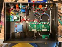
I made a single change that seems to help ALOT, adding a "ground loop breaker" consisting of 10Ω 5W resistor in parallel with a 0.1µF X-rated capacitor. Currently, only the amp board is connected through the "breaker", the speaker and headphone commons are still directly to the chassis.
Is this the correct way?
Hi does your amplifier have RC filters on the inputs? From the pictures it seems these have been omitted. Please don't put caps directly on the inputs but use RC filters instead. This is the way to get rid of RF/HF pick up and it is nowadays a must in any decent design. All this BEFORE the volume controller.
No but I'd like to add some RC filters. Is there a "standard" recommendation for part selection?
I did some searching and found various answers
You know what they they about assumptions
If you only use that DAC measuring DC offset is advisable. As the amplifier has input caps (the white ones) after the volume control DC has little influence except for the potentiometer that may scratch IF there is DC. Don't worry if it is just a few mV.
The white caps are the coupling caps between the amp stages, but either way it sounds like I'm covered from this aspect.
As mentioned above the ground loop seems to have removed most of the noise I was referring to in the OP. There is now the faintest of noise which I'm hoping maybe the RC filter will help with.*EMI from the PC is a gift you get for free when using a computer. You can bother a lot (please note pc's are a known source of RF and they often pose a ground loop as a bonus) or go the simple way and simply use the streamer.
Thanks so much for the kind words!Your way of building/constructing is a joy to the eyes!
If it is a "hashy noise" and no mains related hum, there is no point in troubleshooting the source of hum.
I found tube caps are totally uneffective (aluminium or steel, all the same). Tested on sensitive phono input tube, it did not make any difference with or without. Perhaps they are of use on VHF.
If there is no significant noise with the following three conditions
- open circuit inputs
- shorted inputs
- L and R inputs connected together with an interconnect cable
(with min and max volume setting each test above)
then the source of noise is external. It is still possible that DC is flowing through the input. You can easily measure DC voltage at the input socket. Source output or your input should be AC coupled, by a capacitor or transformer.
I made a single change that seems to help ALOT, adding a "ground loop breaker" consisting of 10Ω 5W resistor in parallel with a 0.1µF X-rated capacitor. Currently, only the amp board is connected through the "breaker", the speaker and headphone commons are still directly to the chassis.
Is this the correct way?
I'm sorry I wasn't more clear. What was meant is the system grounding arrangement. (Your internal star grounding is perfectly conventional and complete. Star grounding is a fallacy, but that's a separate matter if we're lucky.) Everything connected to your amplifier is also connected to AC power (usually), so these other connections matter, and none are unimportant. Hence my request to isolate as a means of zeroing in on the culprit.
The general rule is: there should be one and only one path for signal current flow. If this cannot be done for some (very, very good) reason, then the loop should be as short as possible.
There's no reason to bypass the 10R signal ground to chassis resistor; it just defeats its purpose.
Isolate the source and amplifier from everything else, plug them into the same power strip, and let us know how it goes.
All good fortune,
Chris
If there is no significant noise with the following three conditions
- open circuit inputs
- shorted inputs
- L and R inputs connected together with an interconnect cable
(with min and max volume setting each test above)
Yes amp is basically silent in all of these conditions.
I'm sorry I wasn't more clear. What was meant is the system grounding arrangement. (Your internal star grounding is perfectly conventional and complete. Star grounding is a fallacy, but that's a separate matter if we're lucky.) Everything connected to your amplifier is also connected to AC power (usually), so these other connections matter, and none are unimportant. Hence my request to isolate as a means of zeroing in on the culprit.
The general rule is: there should be one and only one path for signal current flow. If this cannot be done for some (very, very good) reason, then the loop should be as short as possible.
There's no reason to bypass the 10R signal ground to chassis resistor; it just defeats its purpose.
Isolate the source and amplifier from everything else, plug them into the same power strip, and let us know how it goes.
The amp is connected to a Tripp-Lite ISO bar surge protector, along with an LCD monitor, powered HUB, PC, laptop charger. The DAC is USB-powered from the PC.
Here are my findings:
- Noise is still present when everything from the power strip is removed except the amp and PC or powering the DAC with external power from wall-wart (so only relying on PC for USB data).
- Amp is silent with the "ground loop breaker" (pictured) and above setup.
- Also, amp is silent WITHOUT the "GLB" when the DAC is connected to an RPI streamer (w/ Hifiberry Digi+ via Optical)
It's fairly safe to say the PC is injecting some nasty noise when used.
Using the streamer is not a long term option because I also want to play things directly from the browser.
I think that the ground loop breaker is a good long term solution as it can mitigate issues if the amp gets moved around or sold to a new owner (which happens often with my gear), but I temporarily removed it as I wasn't sure if the way I had it was entirely safe.
i.e, if high-voltage from the PSU touches the chassis, if the loop is entirely closed.
I used the resistor and cap based on the information on one of the amb.org projects.
The ground loop breaker is also described in section 9 of this page: Earthing (Grounding) Your Hi-Fi - Tricks and Techniques
The loop breaker works by adding a resistance in the earth return circuit. This reduces circulating loop currents to a very small value, and thus 'breaks' the loop. The capacitor in parallel ensures that the electronics are connected to the chassis for radio frequency signals, and helps to prevent radio frequency interference. Finally, the diode bridge provides the path for fault currents.
I didn't have the diode bridge, which sounds critical for safety?
In my Pass Pearl 2, lifting the ground was done only with the 35A diode.
In the Pass F5, an ICL was used...
So not very clear what is sufficient here.
Attachments
Last edited:
There's no reason to bypass the 10 Ohm signal ground to chassis resistor; it just defeats its purpose.
Please explain that (as it is wrong).
So not very clear what is sufficient here.
A large 10R resistor is sufficient to open a usual fuse in the power supply's primary feed, so is good enough for a catastrophic failure in the secondary (signal) side of the power transformer. It's not sufficient to trip the house breaker in the case of a primary winding failure to signal ground, which is the reason such big diodes are used. They need to be big enough to survive long enough to trip the house breaker.
Neither kind of ground loop breaker should ordinarily be bypassed because their purpose is isolation. IMO RF interference issues should be dealt with by filtering (whatever) to signal ground rather than chassis.
All good fortune,
Chris
The amp is connected to a Tripp-Lite ISO bar surge protector, along with an LCD monitor, powered HUB, PC, laptop charger. The DAC is USB-powered from the PC.
Here are my findings:
- Noise is still present when everything from the power strip is removed except the amp and PC or powering the DAC with external power from wall-wart (so only relying on PC for USB data).
- Amp is silent with the "ground loop breaker" (pictured) and above setup.
- Also, amp is silent WITHOUT the "GLB" when the DAC is connected to an RPI streamer (w/ Hifiberry Digi+ via Optical)
Cool. A complete survey of grounding in the system would include mention of all copper connections, signal, safety earth, and any externals, any copper connections to the greater outside world. Then, these would be drawn in a little schematic for study.
You've already correctly diagnosed and solved the issue. What I'm trying to encourage, for all of us since this is a public forum, is to take the time to draw out this little schematic. Once this is done, grounding loops become crystal clear and folks won't need to experiment (hopefully!) or trust to internet lore. They'll see for themselves, and will only need to research the best safe solution.
A final note: isolating signal ground from safety earth ground is not risk-free. The double-double-diode standoff is well accepted in the DIY community, but I'd bet again UL approving many implementations. Pure Class 1 with signal transformers for isolation raises no red flags and is the gold standard. Costs good money to do right, but throws in RFI filtering and universal compatibility.
All good fortune,
Chris
Last edited:
Thanks for the information and tips. I think a complete survey is a bit beyond my current knowledge but I'll definitely look into it.
There are a few posts from a few years ago that Wayne and Nelson Pass mention that the diode bridge solution passes CSA approval:
https://www.diyaudio.com/forums/pas...idge-loop-breaker-question-5.html#post4916530
> with signal transformers for isolation
are you referring to 1:1 input transformers, such as these?
My #1 priority with a power amp (and especially tube amp build) is safety.
If direct wire from signal ground to chassis is the safest option, I prefer that and will need to find a different way to solve the issue.
I read in one of the posts that adding the 10R resistance in the input wiring ground could have similar effect?
There's an amazing amount of mistaken (or maybe just outdated) stuff early on in that thread, but Nelson Pass' crew are solid and should be trusted over anything I say, among others.
Jensen transformers have earned their reputation. Gold standard.
I actually don't believe that a grounding schematic is beyond any interested DIYer's capabilities. All of the connections of interest can be tested with a simple continuity meter, and we all have $18 DVMs in the car toolkit. Only "galvanic" * connections matter, and can all be "Ohmed out" (boomer speak for continuity tests). We need to look at each piece of the puzzle, determine which external connections each has, and which are internally connected "galvanically" *.
* I love the origin of this word, which includes ships of the British Navy, dead Italian frogs, and is also the origin of "galvanized", in the sense of being shocked into action by an external impulse. From the really, really old days when folks were just discovering chemical batteries.
Isolating *only* the input stage's signal ground, meaning separating it from the rest of signal ground, works to the extent that the input stage's input is truly differential, e.i. itself independent of signal ground. This is part of a larger discussion about why single-ended non-differential signal paths are such a Royal Pain. Especially for folks like you with stringent requirements, but measuring equipment is just as worse.
All good fortune,
Chris
Last edited:
I think there is a misunderstanding about the bypassing off the 10Ω (not 10R) resistor. Itsikhefez mentions using a 10Ω 5W resistor in parallel with a 0.1µF X-rated capacitor. I don't think OP uses a switch or whatever to short that 10Ω resistor!? That capacitor is in parallel which may also be called "bypassing" the resistor but the X-rated capacitor clearly has a function....
So a lot of words but IMO because of a misunderstanding or misinterpretation.
@Itsikhefez: whatever you do ... when the chassis is connected directly to PE you have done the minimum that is required. All the choices focus on Audio GND and its connection to PE. As you have found out a direct connection of Audio GND to PE creates more problems than it solves. It will occur for sure when every device in the chain has a direct connection of Audio GND to PE as is common in anglosaxon countries. This is a very known fact when one repairs audio stuff and solves ground issues but ... you will meet people that will react and object to any attempt of you lifting Audio GND from PE. Mentioning you will have a floating Audio GND will even cause excommunication by the community. BTW forget about the UL as it is DIY and you are not a manufacturer.
So resume: you have experienced that connecting Audio GND straight/directly to PE is NOT the way to go. We should focus on creating a more or less standard to solve this and I think there are already enough solutions that prove the old standard is simply outdated for audio. Nevertheless the old standard is etched in minds and so common that it seems fighting with windmills
Last edited:
Here we must disagree. Safety is not about UL or even about you and me. Nobody gives a rat's behind if you or I hurt ourselves. Our friends will look sorrowful for a few weeks, then go chat up the pretty widow. Later, we'll be given a Darwin Award and a chuckle.
Safety is for family, friends, pets. We must always take due responsibility. We couldn't live with ourselves if we did less than our best, and someone else got hurt.
Call me a Safety Sally if you will, but when I show new shooters about firearms, I tolerate no casual disregard of any of the four firearm safety rules. Driving instructors should be just as strict. I suggest that in this public forum we should all be just as strict. Fun, challenging, and safe.
All good fortune,
Chris
You don't react to my post. I know about safety sir. Problem is I also know about grounding and the misconceptions around it.
I don't know anything about fire arms and wish to keep it that way. Fire arms are apparently very safe but still people die often from their own weapon for some reason. This new subject will only create more confusion in a thread about a very nice built device by a competent DIYer that wants knowledge to solve noise/hum issues.
I don't know anything about fire arms and wish to keep it that way. Fire arms are apparently very safe but still people die often from their own weapon for some reason. This new subject will only create more confusion in a thread about a very nice built device by a competent DIYer that wants knowledge to solve noise/hum issues.
Last edited:
- Home
- Amplifiers
- Tubes / Valves
- Noise pickup in tube amp, increases with volume