I've linked an article from 1953 by Hafler and Keroes showing ultraiinear operation of 6L6/807/KT66 at ~400V plate to cathode, using 43% taps (by voltage ratio). The 807 is rated at 400V for triode operation in the datasheet, but only 300V for tetrode operation. Also linked ultralinear curves.
https://dalmura.com.au/static/Radio-News-1953-02.pdf
The 807 Tube
So it seems in practice it works OK in ultralinear at screen voltage > 300V.
https://dalmura.com.au/static/Radio-News-1953-02.pdf
The 807 Tube
So it seems in practice it works OK in ultralinear at screen voltage > 300V.
Years ago I built a breadboard with 4 5B25xx in ultralinear with 500V on the anodes and screens. Didn't run it for long but got well over 100W from a quad. The 470R 2W screen resistors showed signs of overheating after some crazy full power sine wave testing. The blue glow on the glass was pulsing and the OPT was singing so I stopped there. I would say with most 807/6L6oids you will be fine at 400V in UL using music. Full on flat out sine wave testing may be a bit harsh.
I also strapped them as triodes and drove them with MOSFET followers for AB2. Easy 100W and no stress. I'm guessing here as I didn't measure it but in UL the screen voltage can still go above the anode voltage due to resistance in the primary of the OPT and the screens being closer to the CT as the anode is pulled down. So not quite like triode but it should be fine at 400V.
Cheers
Matt
Thanks for everyones input, I think I have an idea where to go from here on.
My main concern is power supply right now, I was going to go with a tube rectifier for the hell of it and looks like a GZ34 is the best option, but is it enough?
I want a bit to come and go on and looking at the datasheet, the maximum plate current in AB1 is 120mA for a pair, so 2 channels will almost max out the rectifier input, plus the PI tubes, etc will need a little power, of course this is only the maximum rating at full volume, plus there are losses, etc, so not sure what the total power requirements will be?
I thought 280mA would be safer, but not much rectifier options are there, especially with low voltage drop.
Perhaps dual rectifiers could be an option?
Im looking at about 25-30 watts per channel in AB1, but not sure how much this is reduced by running in UL.
By the looks of it on the charts im looking at, its not reduced a hell of a lot.
I see a few builders add a switch to switch between UL and triode operation, and even pentode/tetrode operation on some amplifiers, IDK if there is much advantage to this, but its more probably useful as an educational/experimental standpoint, gives you essentially a second amplifier in one.
Ive been reading a few other threads on this and it seems there are a fair few running 6L6 in UL mode perfectly fine, so not too sure where this idea came about that 6L6 is not suitable for UL operation, but seems to be a discussed topic for whatever reason.
All i know is in theory its just a beam tetrode, so if KT88, 6V6 and other similar tubes can run in UL, then 6L6 is no different!
Well yes I see that now, although note it doesnt say peak to peak, its "grid1 to grid1" which im assuming implys the same thing if you are talking about the voltage difference between both tubes, that makes total sense.
Yes this confirms what im reading in other threads too.
Thats also how I understand it to be regarding UL operation, and is the reason that the screen voltage does not matter if running in UL
My main concern is power supply right now, I was going to go with a tube rectifier for the hell of it and looks like a GZ34 is the best option, but is it enough?
I want a bit to come and go on and looking at the datasheet, the maximum plate current in AB1 is 120mA for a pair, so 2 channels will almost max out the rectifier input, plus the PI tubes, etc will need a little power, of course this is only the maximum rating at full volume, plus there are losses, etc, so not sure what the total power requirements will be?
I thought 280mA would be safer, but not much rectifier options are there, especially with low voltage drop.
Perhaps dual rectifiers could be an option?
Im looking at about 25-30 watts per channel in AB1, but not sure how much this is reduced by running in UL.
By the looks of it on the charts im looking at, its not reduced a hell of a lot.
I see a few builders add a switch to switch between UL and triode operation, and even pentode/tetrode operation on some amplifiers, IDK if there is much advantage to this, but its more probably useful as an educational/experimental standpoint, gives you essentially a second amplifier in one.
I'm curious...
Since the 807 (and older pre-"GC" 6L6) have screen grid limited to 270V, wouldn't one be able to use these with a UL OPT if the plate supply is kept down at 270V to maybe 300V? While you won't get anywhere near max power that way, you could get perhaps 15W, with good damping (by running the pentodes at low voltage on the plate/screen grid but relatively high current, perhaps Vp,sg = 300V and Ip+sg = 75mA). A lower impedance primary could also be used for the OPT, which potentially makes design and manufacture easier/cheaper.
Is there a reason other than being limited to low output power that this will not work?
Also, how different is the screen grid construction of an 807 from the 7027A? The 7027A was pitched for use with UL OPTs, and it's basically similar to a 6L6GC (I'm not sure there is any difference, actually).
Honestly curious, which is why I ask. Thanks.
Ive been reading a few other threads on this and it seems there are a fair few running 6L6 in UL mode perfectly fine, so not too sure where this idea came about that 6L6 is not suitable for UL operation, but seems to be a discussed topic for whatever reason.
All i know is in theory its just a beam tetrode, so if KT88, 6V6 and other similar tubes can run in UL, then 6L6 is no different!
The data sheet clearly said peak to PEAK grid voltage. Not just one peak, but twin peaks.
Think about it. The peak grid voltage is what is required to overcome the BIAS and take g1 to zero. You may actually clip at a bit less depending on your load line, which for a real speaker is elliptical and variable. So you do want a bit of overhead. Whatever vg1 you set the bias to is what you need to drive it with, give or take a volt or two. Then you don’t even really need a data sheet to determine your output stage gain or drive requirement. Set it deeper into AB and it takes less drive for full output, with the penalty being heat.
Ham radio operators often run true class B or C, possibly very low or even zero idle bias to get efficiency and the most possible output power. The g1 bias is more negative. And they often run into positive g1 territory to get even more power. That not only requires the extra voltage (maybe another 10 volts), but the driver stage must also provide g1 current. The usual capacitor coupled stages cannot do this - direct or transformer coupling is required. Most audio amps with pentodes run AB1 (or B1) because there are other ways of getting the extra current (ie, increase Vg2) and do not require a special driver stage to do this. The 807 (and 6L6 variants) were designed to take vg1 current with no damage but others audio pentodes may not be. Most audio amps I’ve seen here that run AB2 use triode outputs, where the positive g1 drive gets you similar output voltage swing to pentodes - eliminating the usual efficiency penalty associated with them.
Well yes I see that now, although note it doesnt say peak to peak, its "grid1 to grid1" which im assuming implys the same thing if you are talking about the voltage difference between both tubes, that makes total sense.
I can say I have run the 1625 which if the 12 volt version of the 807 UL for a few years without problem.
Operating with the Dynaco A470 transformer with about 410 volts. Likely about 400 volts on the plate and screens. Main use was as a car amplifier above 100HZ.
You have to remember that we are mostly worried about total screen dissipation when considering the voltage limit. Screen grid current increases as the plate voltage swings lower than the screen and towards 0 volts. With UL, the screen voltage drops with the plate so the worst case screen dissipation will not be as bad.
Yes this confirms what im reading in other threads too.
Thats also how I understand it to be regarding UL operation, and is the reason that the screen voltage does not matter if running in UL
I did a quick simulation last night for 807 in ultralinear at 400V, 6.6k output transformer, and yes you are looking at 25-30 watts. Fixed bias (plate voltage 400V, cathode 0V) looked to have quite a bit lower distortion than cathode bias with a shared resistor (plate voltage ~440V, cathode ~40V).
I did a quick simulation last night for 807 in ultralinear at 400V, 6.6k output transformer, and yes you are looking at 25-30 watts. Fixed bias (plate voltage 400V, cathode 0V) looked to have quite a bit lower distortion than cathode bias with a shared resistor (plate voltage ~440V, cathode ~40V).
Is 6.6K the correct impedance for a pair?
I thought it was 4.2K?
Regarding fixed bias, from reading other peoples experiences, fixed bias doesnt sound that great, presumably in a HiFi situation, I know for guitar, my 807 amp sounds great with fixed bias.
See post #89 here:
807 Sound Quality?
Is a shared cathode resistor ideal? As far as i understand its to balance the tubes better if its not a perfectly matched pair.
Regarding 807 plate voltage, it seems that they like at least 400V, but their sweet spot is somewhere between 400 - 450V
Im tempted to run it closer to 450V or somewhere in between.
Last edited:
I was basing the 6.6k on the Hafler and Keroes article. I did check at ~5k and it was OK there as well, a bit more power at slightly higher distortion. 6.6k is closer to class A. Obviously there is some flexibility in operating point. The shared cathode resistor was from the same article, I can try with individual resistors as well.
I can't comment on sound quality with fixed bias, but the distortion figures in the datasheet are typically lower with fixed bias compared to cathode bias.
I can't comment on sound quality with fixed bias, but the distortion figures in the datasheet are typically lower with fixed bias compared to cathode bias.
nzoomed, you might check out:
The 1625 amp, Mk. II | Audiokarma Home Audio Stereo Discussion Forums
The 1625 amp, Mk. II | Audiokarma Home Audio Stereo Discussion Forums
I was basing the 6.6k on the Hafler and Keroes article. I did check at ~5k and it was OK there as well, a bit more power at slightly higher distortion. 6.6k is closer to class A. Obviously there is some flexibility in operating point. The shared cathode resistor was from the same article, I can try with individual resistors as well.
I can't comment on sound quality with fixed bias, but the distortion figures in the datasheet are typically lower with fixed bias compared to cathode bias.
OK, I didnt realise that it was different depending on what class you are running.
Ive always gone with the 4K figure that i had years ago and had been using 2K on my guitar amp running a quad of the things.
Also had been going by the specs from Hammond's product line which were listed as 4.2K
Question is whats the optimal impedance for Class AB1?
nzoomed, you might check out:
The 1625 amp, Mk. II | Audiokarma Home Audio Stereo Discussion Forums
Thanks, ill take a look
Perhaps draw a loadline if the 'optimal' aim is for max power? Then measure your amp's output and vary the load resistance on either side to find your actual optimum. Then find a speaker that acts like your optimal resistance.Question is whats the optimal impedance for Class AB1?
Perhaps draw a loadline if the 'optimal' aim is for max power? Then measure your amp's output and vary the load resistance on either side to find your actual optimum. Then find a speaker that acts like your optimal resistance.
Are there any charts out there with this data?
6l6 is a common tube, I thought the impedance for AB1 should be well documented?
I would be using just standard 8 ohm speakers that I currently use, so I will likely wind a 8 ohm secondary so that I can make full use of the secondary winding.
I dont even know where to begin drawing a loadline.
I'm reading about it here. Seems quite technical.
The Valve Wizard -Push-Pull
Another perspective: there is no such critter as "the correct loadline". There are various resistive loadlines that very, very roughly approximate an actual working, real speaker loadline. But we all love models, it's in our human DNA, so we trudge on.
Loadlines in old tube manuals are chosen to optimize (essentially always) power output into a hypothetical resistive load. If that's your goal and if that's your actual load, you're golden - done deal.
But if your goal is lowest distortion, or best reactive load drive capability, or best speaker damping, or best output transformer characteristics to accommodate that chosen ratio, or widest bandwidth with a given output transformer construction (cost), or something else, then the ideal may vary from databook examples.
The good news is that our ignorance of the actual requirements (because of our ignorance of the actual load that will be presented) doesn't matter too much. We love to compulse about imaginary resistive loadlines, but it's largely semi-wanking.
Just another opinion,
Chris
Since Hafler and Keroes invented ultralinear operation using the 6L6GB, you can be pretty sure that 6.6k is about right for the 807. I have seen references to 6.6k-7.6k and modelling confirms that. This for plate-cathode voltage of ~400V and bias of 50-60 mA.
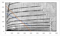
For tetrode operation at 400V plate, 300V screen, a 6k load line looks good (see attachment), but everything that Chris says above is true") .
.
For tetrode operation at 400V plate, 300V screen, a 6k load line looks good (see attachment), but everything that Chris says above is true
.Attachments
Another perspective: there is no such critter as "the correct loadline". There are various resistive loadlines that very, very roughly approximate an actual working, real speaker loadline. But we all love models, it's in our human DNA, so we trudge on.
Loadlines in old tube manuals are chosen to optimize (essentially always) power output into a hypothetical resistive load. If that's your goal and if that's your actual load, you're golden - done deal.
But if your goal is lowest distortion, or best reactive load drive capability, or best speaker damping, or best output transformer characteristics to accommodate that chosen ratio, or widest bandwidth with a given output transformer construction (cost), or something else, then the ideal may vary from databook examples.
The good news is that our ignorance of the actual requirements (because of our ignorance of the actual load that will be presented) doesn't matter too much. We love to compulse about imaginary resistive loadlines, but it's largely semi-wanking.
Just another opinion,
Chris
I think your right going by what im reading elsewhere too.
Also seems common that guitar amps quite often will use a different impedance compared to hifi situations and thats understandable.
I have been looking at this guide for building a williamson amp using 807 and it specifys a Stancor A8072 transformer for UL operation
http://www.tubebooks.org/file_downloads/stancor_ul_schematics.pdf
The specs for that transformer is 7.6K I thought that may have been high going by what is being thrown around, but the datasheet seems to support this impedance if im running at that voltage which I intend to do somewhere around 440V
Reading back, it appears the figure of 6.6K is for class A, so if thats the case 7.6K seems about right from what I cam make out of it all.
Would you go with this if you had the means to wind your own transformer?
I have a bunch of winding machines, bobbins and rolls of wire, so Im sorted as far as that goes.
With a real speaker load there would be little difference between 6.6k and 7.6k, anything around there will be fine. You're keen to wind your own transformer, hopefully you can track down a suitable winding diagram to follow. I've attached an edited load line for the tetrode connection, I stuffed up the class A loadline (blue line) in post #53.
Attachments
I am curious, too. Cathode bias has less anode voltage swing, because an increasing Ik drops higher voltage on Rk, which makes the cathode more positive, when the voltage on the anode voltage decreases, but it should not reach the cathode. I would leave 50V between them at peak Ik.I'm curious...
Since the 807 (and older pre-"GC" 6L6) have screen grid limited to 270V, wouldn't one be able to use these with a UL OPT if the plate supply is kept down at 270V to maybe 300V? While you won't get anywhere near max power that way, you could get perhaps 15W, with good damping (by running the pentodes at low voltage on the plate/screen grid but relatively high current, perhaps Vp,sg = 300V and Ip+sg = 75mA). A lower impedance primary could also be used for the OPT, which potentially makes design and manufacture easier/cheaper.
Is there a reason other than being limited to low output power that this will not work?
Also, how different is the screen grid construction of an 807 from the 7027A? The 7027A was pitched for use with UL OPTs, and it's basically similar to a 6L6GC (I'm not sure there is any difference, actually).
Honestly curious, which is why I ask. Thanks.
I dissected a 807 tube, here are the photos:
G-807 - Google Photos
BTW, I think one should be flexible about static operational parameters, like B+, Vg1, Vg2, UL tap. I successfully operated the 807 in triode mode with 425V B+ with 25:1 OPT. The 53% UL tap is a myth. In my design I have a transformer with 5 primary sections, and this makes it possible to test 0, 20, 40, 60, 80, and 100% UL tap, i.e pentode mode, triode mode, and four different UL taps. Also I never set the operating point beyond 20W idle dissipation. But my goal is not maximum possible output power, 15W is sufficient. 15W or 150W? There is bigger sensitivity variation in a frequency response of a typical loudspeaker than that 10dB difference.
With a real speaker load there would be little difference between 6.6k and 7.6k, anything around there will be fine. You're keen to wind your own transformer, hopefully you can track down a suitable winding diagram to follow. I've attached an edited load line for the tetrode connection, I stuffed up the class A loadline (blue line) in post #53.
Thanks for that.
Ive got a bunch of winding gear I acquired from a guy I know who used to run a business winding transformers, so I have literally everything I need to make a lifetime supply of transformers.
I will see what info I can find on making them, but at this point its a matter of experimentation.
> whats the optimal impedance for Class AB1?
Many loads can work well depending on your power supply. The extended EL34 datasheet shows push-pull values from 3.4k to 11k. (Note that Philips' "class B" here is really well toward class AB and are fine audio conditions.) The 6L6(GC) recommendations are limited partly by the lower max plate voltage, but mainly by marketing (they were selling higher-price tubes and did not want us thinking the 6L6 could do big work). With one exception the 6L6 conditions go back to the 1930s metal 6L6.
Many loads can work well depending on your power supply. The extended EL34 datasheet shows push-pull values from 3.4k to 11k. (Note that Philips' "class B" here is really well toward class AB and are fine audio conditions.) The 6L6(GC) recommendations are limited partly by the lower max plate voltage, but mainly by marketing (they were selling higher-price tubes and did not want us thinking the 6L6 could do big work). With one exception the 6L6 conditions go back to the 1930s metal 6L6.
Last edited:
With a real speaker load there would be little difference between 6.6k and 7.6k, anything around there will be fine. You're keen to wind your own transformer, hopefully you can track down a suitable winding diagram to follow. I've attached an edited load line for the tetrode connection, I stuffed up the class A loadline (blue line) in post #53.
Then you ought to be able to save a fortune building tube amplifiers. The iron is the most expe$ive part. You have laminations and end bells too? Jealous.
Yes Ive got boxes of laminations and rolls and rolls of wire and boxes of bobbins, i hardly have any space for it so am having to build shelves in my garage and set up a new workbench. The laminations weigh a ton!
This was one of the main reasons I bought the gear, as transformers are the most expensive part of an amp!
Im hoping i can eventually make and sell custom transformers and that way it can help pay for my hobby.
> whats the optimal impedance for Class AB1?
Many loads can work well depending on your power supply. The extended EL34 datasheet shows push-pull values from 3.4k to 11k. (Note that Philips' "class B" here is really well toward class AB and are fine audio conditions.) The 6L6(GC) recommendations are limited partly by the lower max plate voltage, but mainly by marketing (they were selling higher-price tubes and did not want us thinking the 6L6 could do big work). With one exception the 6L6 conditions go back to the 1930s metal 6L6.
Thats good to know.
Something ive only really just learned here is how plate load impedance varies depending on the voltage, im im running closer to 450V is there any advantage on going higher in impedance?
- Home
- Amplifiers
- Tubes / Valves
- Using 807s in a mullard 5-20 circuit