I'm currently testing the first channel of my El Cheapo.
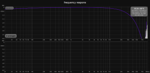
Attached are the first test results using REW. I _think_ my frequency response is quite ok, but my THD(+N) is quite high. Is that correct?
I would love to provide more info, but my level of experience is holding me back. I have no idea what I should tell you... One thing that struck me is that I can lower the THD quite a bit at the expense of noise by lowering the input signal.
Does anyone have some advice? Some handy documentation?
Thanks in advance.
Attached are the first test results using REW. I _think_ my frequency response is quite ok, but my THD(+N) is quite high. Is that correct?
I would love to provide more info, but my level of experience is holding me back. I have no idea what I should tell you...
One thing that struck me is that I can lower the THD quite a bit at the expense of noise by lowering the input signal.Does anyone have some advice? Some handy documentation?
Thanks in advance.
Attachments
At what output power are the distortion measurements taken (Vrms ^2 / load resistance)?
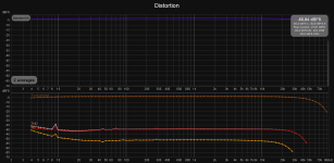
-40 dB THD is 1% which is probably about right near full output power with not much negative feedback. Is it the standard El Cheapo (12at7 LTP into 12aq5's triode connected) or something else?
You could try doing a swept sine test at different levels to get distortion vs power graphs (latest version of REW will do this).
The power level was at less than 1 Watt, don't know the actual number.
No, it's not a 'standard' El Cheapo:
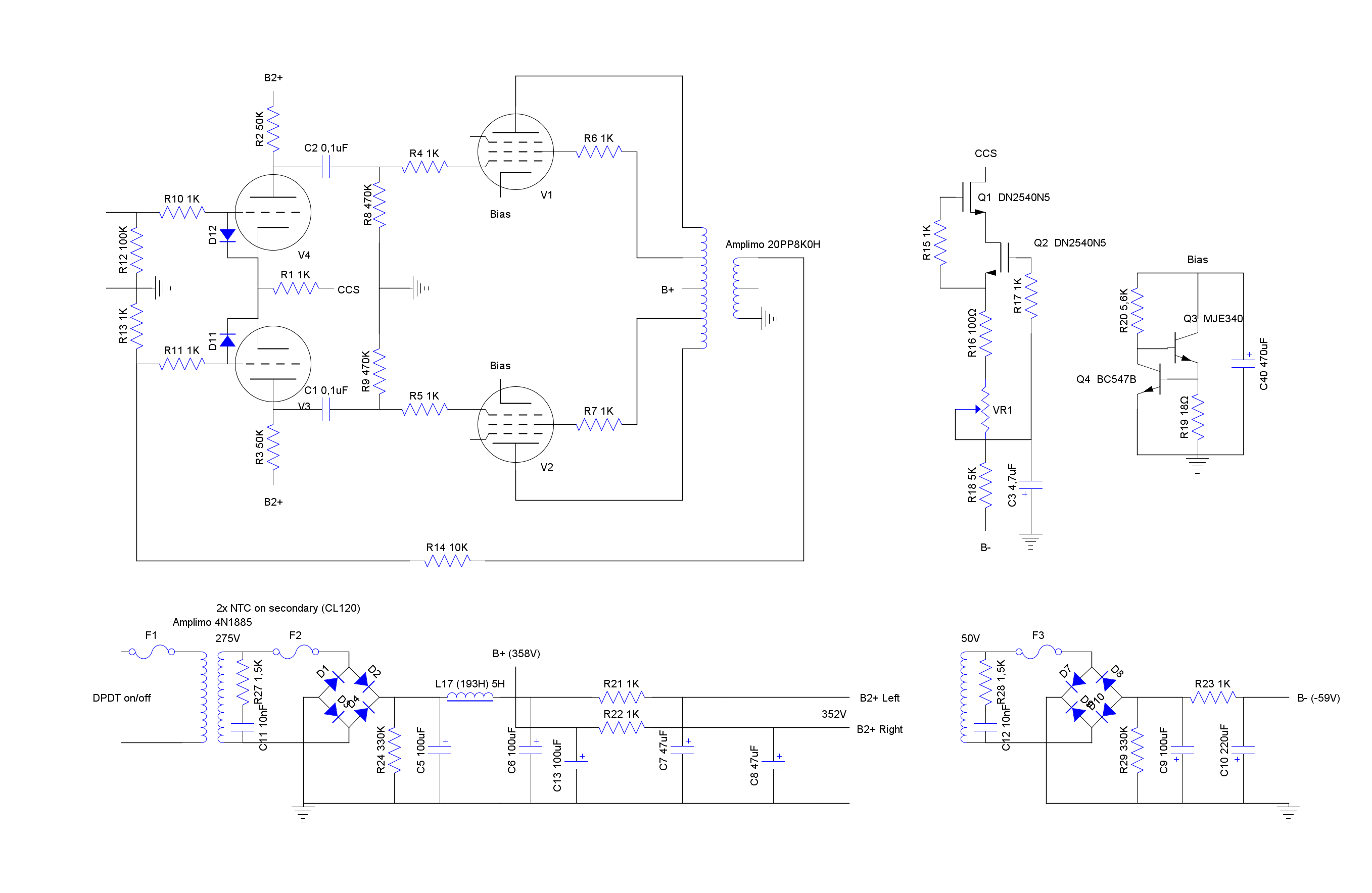
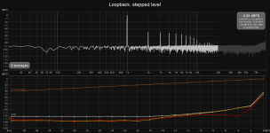
Attached is the swept sine test at different power levels. ±1Vpp is -8.56dbFS (y-axis) is about 0.016W in 8R. I hope I'm doing something very stupid.
No, it's not a 'standard' El Cheapo:
Attached is the swept sine test at different power levels. ±1Vpp is -8.56dbFS (y-axis) is about 0.016W in 8R. I hope I'm doing something very stupid.
Attachments
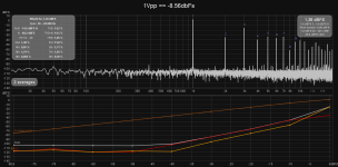
With REW you have to measure the output voltage to the load at a particular input level then enter that to calibrate. Then you can enter the load resistance and REW will automatically calculate power and display directly on the X axis. Sorry I'm away from my computer at the moment so can't tell you exactly where to find all this. The distortion spectrum in your graph would be with the output driven well into clipping.
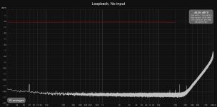
I've taken a step back and am testing my DAC/ADC in loopback. I've calibrated the DAC and ADC.
DAC F(ull)S(cale) output is 1.102Vrms measured by a multimeter, which matches the specs (+3dBu). 0dBu = 0.775Vrms -> +3dBu = 10^(3/20) x 0.775 = 1.0947Vrms.
To measure the same voltage on the input of the ADC, FS has to be 1.213Vrms when measured with the scope in REW. Also the levels part of REW indicates that: the input is 0.83dBFS lower: 10^(0.83/20) x 1.102Vrms = 1.2125Vrms
I haven't been able to find where to enter the load resistance in REW yet. Will investigate further.
I'm not voltage dividing the output. My loadbox is still under construction and it will not divide nor protect (yet).
The DAC/ADC shows quite some noise above the audio bandwidth. I can set the option to enable the high and low pass filters in the distortion settings (of RTA) and these affect the noise figure enormously.
The noise floor of the DAC/ADC rises enormously, mostly in the last 2.0 dBFS. Audio Science Review mentions something similar: Behringer UMC204 HD Audio Interface Review | Audio Science Review (ASR) Forum
Attachments
Last edited:
I have the same interface, my voltage divider is set up to max out at about -3dBFS at worst case.
The load resistance input is found in RTA Window / graph controls / Appearance / "Ref resistance for dBW (ohm)"
Calibrating the voltage level in the Generator window, first set the output at say -6 dB, click on "Calibrate level", measure the level across your load (not the input level) then enter it and click the "Calibrate" button.
Ref resistance set.
Generator was already calibrated.
I'm using the inserts.
Both the DAC and ADC are causing the rise in THD+N. Good idea about the voltage divider. Will think about it. Loadbox will have leds protecting against and indicating overload.
Now back to work. That day time job is getting in the way. Again...
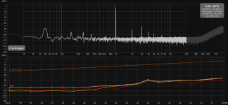
It's late, so the results are preliminary, but I think I solved it. See attachments. Power still below 1W, as I still need to build my attenuator and keep my ADC from clipping.
I'm a bit embarrassed, so 'said and kept silent': The fuse in the B- supply was blown. It looked ok-ish, but had infinite resistance.
I'm a bit embarrassed, so 'said and kept silent': The fuse in the B- supply was blown. It looked ok-ish, but had infinite resistance.
Attachments
The noise floor of the DAC/ADC rises enormously, mostly in the last 2.0 dBFS. Audio Science Review mentions something similar: Behringer UMC204 HD Audio Interface Review | Audio Science Review (ASR) Forum
That's probably the noise shaping of the DAC or ADC. If you're measuring within the audio band, you can choose not to care. If you're looking at integrated noise, I suggest enabling a 20 kHz AES17 filter in software.
You can push the breakpoint for that noise up by increasing the sampling rate. That also increases your FFT bin width, so the noise floor will appear higher.
Tom
I'm back...
In the mean time I have finished the second channel and been playing music
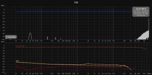
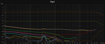
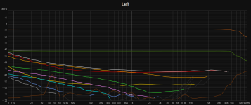
Today I measured both channels; the input was from the same channel of the DAC and the output through the same (resistive 8R) load into the same ADC channel. Output switch was set to pentode UL.
Signal level still low, as my attenuator in the load box is still not ready. ADC clips early, so output level is limited to ~500mV RMS (0.03W).
Legend:
orange-brown: fundamental
red : second (H2)
orange : third (H3)
dark green : noise
light gray : THD + noise
brown : noise floor
Channels are not the same (obviously):
- Right channel has better bass performance (up to ~400Hz)
- Right channel has 10dB less 50Hz hum
- Right has much lower H2 (~15dB)
- Left high frequency H3 is lower (~10dB)
Left channel is closer to power supply and heater wiring for right channel is passing through the right channel (area). That might cause the higher (measured) hum levels in the right channel.
I added a resistor between the output power bias caps and ground. I've read that should lower H3. Does not seem to work really well...
What is your advice? What should I try to improve things? How can I make both channels more similar, preferably the optimal mix from both? Or should I first add attenuation of the load box so we can see how it performs at 1W?
Fire at will!
In the mean time I have finished the second channel and been playing music
Today I measured both channels; the input was from the same channel of the DAC and the output through the same (resistive 8R) load into the same ADC channel. Output switch was set to pentode UL.
Signal level still low, as my attenuator in the load box is still not ready. ADC clips early, so output level is limited to ~500mV RMS (0.03W).
Legend:
orange-brown: fundamental
red : second (H2)
orange : third (H3)
dark green : noise
light gray : THD + noise
brown : noise floor
Channels are not the same (obviously):
- Right channel has better bass performance (up to ~400Hz)
- Right channel has 10dB less 50Hz hum
- Right has much lower H2 (~15dB)
- Left high frequency H3 is lower (~10dB)
Left channel is closer to power supply and heater wiring for right channel is passing through the right channel (area). That might cause the higher (measured) hum levels in the right channel.
I added a resistor between the output power bias caps and ground. I've read that should lower H3. Does not seem to work really well...
What is your advice? What should I try to improve things? How can I make both channels more similar, preferably the optimal mix from both? Or should I first add attenuation of the load box so we can see how it performs at 1W?
Fire at will!
Attachments
For a PP amp, H2 level will be strongly dependent on output tube matching. Try swapping tubes between channels and see what happens. Or just swap one of them and see if you can get left and right more alike. Other than that I would see what it's like at a higher power level before bothering with anything else. Remember most people don't go to the trouble of measuring and live in blissful ignorance .
.I've switched some tubes around...
Right Channel, unless stated otherwise.
Tubes | 50Hz level
1&2 | -80dBFs (left channel)
1&2 | -80dBFs
2&1 | -82dBFs
1&3 | -85dBFs
3&4 | -90dBFs
1&4 | -92dBFs
Tubes | Low frequency THD
1&2 | -45dBFs (left channel)
1&2 | -47dBFs
2&1 | -50dBFs
1&3 | -59dBFs
3&4 | -59dBFs
1&4 | -59dBFs
Tubes | 1kHz H2
1&2 | -76dBFs (left channel)
1&2 | -75dBFs
2&1 | -75dBFs
1&3 | -70dBFs
3&4 | -90dBFs
1&4 | -65dBFs
3&4 seems to be a winner. I'll do some more tests and also give the 6V6's from my guitar amp a try.
I didn't know that, I'll have to look it up. I see a few random spikes there, you get that when the computer has a burst of noise just as the measurement is taken (despite the audio interface being an external usb device). I ended up running REW on linux instead of windows to get rid of that, also using a laptop rather than a desktop.
@tikiroo : it's at the top, just left to RTA, called Overlays.
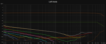
In the mean time I also did a test with the 6V6's in triode mode. Distortion figures look a lot better...
The H3 is quite dominant. I implemented (from the start) the 3rd harmonic distortion suppression scheme (Baby Huey PP EL84 amplifier). Unfortunately, it does nothing in my case as I compared it to the situation without (bypassed by wire).
That would mean that the resistance is wrong for my case, or that the H3 is created somewhere else, right?
Any thoughts? Any guidance?
Is there any concise info about the Western Electric Harmonic Equalizer? What I could find were some forum posts for all kinds of situations. And a few sentences in the 'Valve Amplifiers' book. Not enough to make me understand...
Attachments
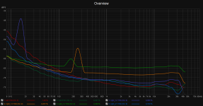
I finally managed to finish one channel of my load box, including attenuation. Besides that I have managed to use a separate DAC and ADC to circumvent the limitations of the Behringer DAC (increasing distortion at higher output levels).
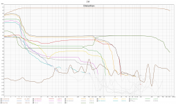
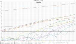
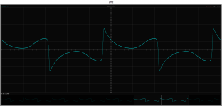
Attached you'll find a distortion vs. power graph and a distortion vs. frequency graph and the waveform of a 1Hz test signal.
So now I have measurements, but instead of answers, I have questions...
Not to much to see in the distortion vs. power graph. What are bad, average, good values btw?
The distortion vs. frequency does show weird things. At least things I don't understand.
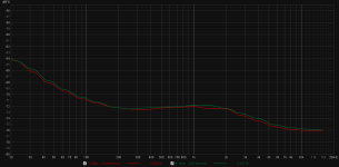
Overal (/fundamental) frequency response seems ok, right?
Very low frequency harmonic distortion is high. Signal looks nowhere near a sine. I think I have seen this shape somewhere; I think it was about transformer saturation caused by a DC imbalance. Could that be the case? If so, how would I solve that? If not, what else could it be?
Between 250Hz and 500Hz the noise increases. What could that be?
Roughly around 1kHz, the distortion becomes way smaller. Is that normal? Is that an indication of a problem (below 1kHz)?
Attached you'll find a distortion vs. power graph and a distortion vs. frequency graph and the waveform of a 1Hz test signal.
So now I have measurements, but instead of answers, I have questions...
Not to much to see in the distortion vs. power graph. What are bad, average, good values btw?
The distortion vs. frequency does show weird things. At least things I don't understand.
Overal (/fundamental) frequency response seems ok, right?
Very low frequency harmonic distortion is high. Signal looks nowhere near a sine. I think I have seen this shape somewhere; I think it was about transformer saturation caused by a DC imbalance. Could that be the case? If so, how would I solve that? If not, what else could it be?
Between 250Hz and 500Hz the noise increases. What could that be?
Roughly around 1kHz, the distortion becomes way smaller. Is that normal? Is that an indication of a problem (below 1kHz)?
Attachments
- Home
- Amplifiers
- Tubes / Valves
- El Cheapo testing