Hi!
I know EL503 tubes are quite rare nowadays and maybe it is stupid to base a new project on them. But some years I got some old guitar amps for free, they were named Faylon P200 and they were not really good sounding amps.
But the amount of power (200watts on 4 tubes!) and pretty special specs in the 4 (!) EL503s in the power stage made me interested to test them out in a diy hifi amp.
They seem to be like one of the last new tube designs before solid state took over! EL520 and EL503 seems to be exactly the same thing by the way.
I got two guitar amps working well and sold those, sold another set of 4 EL503s (I got good money for the last 4...) and I’m now left with remnants from two amps, minus one set of tubes. So 4 EL503s, two PTs and two OPT (IIRC 1.7kohm push pull). Stock they were configured as parallel push pull.
I can’t restore another amp, enclosure and all is so rotten and I’ve already brought two back to life. So I would like to design a hifi stereo amp around these four tubes regardless, just for fun/for teaching myself.
I’m learning designing tube stages based on load lines etc, but I am a rookie right now. I have constructed one ef86+el34 se amp and one el84 push pull just from others schematic. This is my first own design. I’ve heard it described as the last evolution of the EL34, which sounds good if there is any truth to that...
I’d like to hear simple SE amp with these, just one per channel. Maybe hard to get suitable OPT for that? If I understand correctly they do seem to be pretty easy to drive. I have two e80cc that i could use as drivers, maybe need more gain?
I was thinking if anyone else have had this idea before and maybe have a schematic or an opinion on whether or not it could make a good amp or not?
All critisisms are welcome!
Data sheet:
https://frank.pocnet.net/sheets/010/e/EL503.pdf
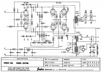
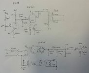
See attached image for schematics of the original guitar amp, notice only one ECC83 for all those power tubes! There is some solid state preamp circuitry before that as well if I remember right.
Best regards,
Lars
I know EL503 tubes are quite rare nowadays and maybe it is stupid to base a new project on them. But some years I got some old guitar amps for free, they were named Faylon P200 and they were not really good sounding amps.
But the amount of power (200watts on 4 tubes!) and pretty special specs in the 4 (!) EL503s in the power stage made me interested to test them out in a diy hifi amp.
They seem to be like one of the last new tube designs before solid state took over! EL520 and EL503 seems to be exactly the same thing by the way.
I got two guitar amps working well and sold those, sold another set of 4 EL503s (I got good money for the last 4...) and I’m now left with remnants from two amps, minus one set of tubes. So 4 EL503s, two PTs and two OPT (IIRC 1.7kohm push pull). Stock they were configured as parallel push pull.
I can’t restore another amp, enclosure and all is so rotten and I’ve already brought two back to life. So I would like to design a hifi stereo amp around these four tubes regardless, just for fun/for teaching myself.
I’m learning designing tube stages based on load lines etc, but I am a rookie right now. I have constructed one ef86+el34 se amp and one el84 push pull just from others schematic. This is my first own design. I’ve heard it described as the last evolution of the EL34, which sounds good if there is any truth to that...
I’d like to hear simple SE amp with these, just one per channel. Maybe hard to get suitable OPT for that? If I understand correctly they do seem to be pretty easy to drive. I have two e80cc that i could use as drivers, maybe need more gain?
I was thinking if anyone else have had this idea before and maybe have a schematic or an opinion on whether or not it could make a good amp or not?
All critisisms are welcome!
Data sheet:
https://frank.pocnet.net/sheets/010/e/EL503.pdf
See attached image for schematics of the original guitar amp, notice only one ECC83 for all those power tubes! There is some solid state preamp circuitry before that as well if I remember right.
Best regards,
Lars
Attachments
That sounds like a fun project! Since it is your first design, a single-ended amplifier is a good choice. There are lots of tutorials available on the web. I like The Valve Wizard -Single Ended
You will have no problem finding a suitable output transformer.
EL503s are not easy to get, but if you run out of tubes, you can easily tweak the design to suit some other more common tube.
Good luck with your project!")
You will have no problem finding a suitable output transformer.
EL503s are not easy to get, but if you run out of tubes, you can easily tweak the design to suit some other more common tube.
Good luck with your project!
I have acquired and/or restored 10+ amplifiers based on EL503, and the idea of building a SE amplifier with the restoration leftovers also comes to my mind sometimes. Most EL503/EL520 amplifiers were meant for voice/guitar amplification at low cost and they obviously have flaws, but I also have a push-pull EL503 amplifier that was meant for general purpose applications and does have quality output transformers: it sounds quite good as Hi-Fi amplifier, altough is not my favourite one.
Before starting your project, I suggest to measure the emission of your spare tubes, because it may be below 60% and you will not even notice on the original guitar amp application unless you take a measurement. You will definitely hear it in a SE Hi-Fi amplifier. The guitar amp output transformer you have is probably not fit for the purpose. There is a further roadblock on the path of a successful EL503 SE amplifier: this tube was never specified nor used for SE applications. To my knowledge, there aren't ready-made EL503/EL520 SE schematics. EL503 drive and B+ supply requirements are similar to EL84. I would start by seeking for PSE EL84 schematics, or building a EL503 power stage according to datasheet suggested values extrapolated from the PP application, and add a preamp stage grafted from a EL84 design.
Before starting your project, I suggest to measure the emission of your spare tubes, because it may be below 60% and you will not even notice on the original guitar amp application unless you take a measurement. You will definitely hear it in a SE Hi-Fi amplifier. The guitar amp output transformer you have is probably not fit for the purpose. There is a further roadblock on the path of a successful EL503 SE amplifier: this tube was never specified nor used for SE applications. To my knowledge, there aren't ready-made EL503/EL520 SE schematics. EL503 drive and B+ supply requirements are similar to EL84. I would start by seeking for PSE EL84 schematics, or building a EL503 power stage according to datasheet suggested values extrapolated from the PP application, and add a preamp stage grafted from a EL84 design.
Last edited:
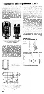
I attach the original 1966 press release of the EL503 tube, from Funkschau (I believe). It is in german, I never found a english translation. It goes on lengt about the unique grid arrangement. This tube has always been expensive, I remember that price for a spare tube was about the same as a BW CRT. Many amplifiers were discarded early, still in good conditions, because a new solid state amplifier was cheaper than worn tubes replacement. Tubes were outdated things at the time, no one was thinking to modify the amplifier to use EL36 or EL34. I guess that a viable approach for a new build today would be to keep the tube way below the maximum ratings, and to basically plan to never replace it. I guess that triode curves would be very linear. This tube is a interesting glimpse of what could have been the evolution of the technology, if semiconductors would not have been developed. Hard to explain why Valvo invested what must have been a significant amount of resources to perfect a product that clearly had no future.
Attachments
Here is some write up about the EL503/EL520 tube. (English Google translate option )
Die EL503 - Story
One thing I see is a frame grid for grid 1 and an ordinary grid for grid 2. This means no aligned grids to lower screen current (and screen current distortion).
You can see the resulting curvature in the individual plate curves on the EL503 datasheet. Obviously it is not a kinkless audio tube design either. The Mazda Belvu datasheet curves (below) have max diss. hyperbolas on them. Most any loadline will be near high distortion kinks. A mystery as to why someone would want to bring this tube back into production for audio. I would recommend getting some triode curves for the EL503 before going SE. Frame grid 1 is no guarantee of good triode curves.
https://frank.pocnet.net/sheets/020/e/EL503.pdf
Last edited:
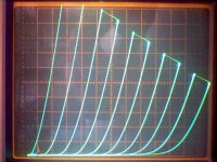
Single ended triode mode seems to be nice according to my preliminary tests, but I lack a curve tracer so I only made a few quick distortion measurements on random working points.
Due to the very high transconductance, EL503 can also work as low power triode SPUD. 200V on the plate+grid (Recom R12-150B dc/dc converter); 390 ohms bypassed cathode resistor (anode current will be 30-33mA); 1K grid stopper resistor on g1 and/or VK200 in series to the anode to avoid oscillations; 1200 ohms load such as 230/16V or 230V/12V 20VA toroidal power transformer (RS components part number 671-9053 or bigger). Lots of fun with a handful of parts. For better and more thought out outcomes, triode curves would be needed.
Due to the very high transconductance, EL503 can also work as low power triode SPUD. 200V on the plate+grid (Recom R12-150B dc/dc converter); 390 ohms bypassed cathode resistor (anode current will be 30-33mA); 1K grid stopper resistor on g1 and/or VK200 in series to the anode to avoid oscillations; 1200 ohms load such as 230/16V or 230V/12V 20VA toroidal power transformer (RS components part number 671-9053 or bigger). Lots of fun with a handful of parts. For better and more thought out outcomes, triode curves would be needed.
Hmm, triode curves look about like a 6L6GC except higher Mu. Not bad, but not great either. About typical for most later beam pentodes, optimised for gm. My first guess for a linear load line was 4000 Ohm, but that is more than the typical 5X Ri, and would only produce a few Watts. (Ri 565 Ohm at 100 mA, so 5X Ri = 2826 Ohm)
A P-P design might be better, reduce 2nd harmonic. Or go for a Mosfet driven UnSET scheme to get less 2nd harmonic and more power.
For the price these tubes seem to go for, I myself would sell them and get something more suited to what is wanted, for future replacement's sake.
A P-P design might be better, reduce 2nd harmonic. Or go for a Mosfet driven UnSET scheme to get less 2nd harmonic and more power.
For the price these tubes seem to go for, I myself would sell them and get something more suited to what is wanted, for future replacement's sake.
Last edited:
Thanks for the EL503 triode curves, I believe that they haven't been published anywhere until now. To get a rough extimate for a design, my reference was the 8417 triode curve because the two tubes have some similarities, but the EL503 real curves shows a higher mu and have a slightly different shape.
The smoking-amp considerations are true, this oddball tube does not fit well the Hi-Fi parameters, when driven at the rated power. This may also explain why it mostly powered guitar and PA amplifiers. On the wast majority of said amplifiers, it was actually driven way harder than the maximum datasheet values, usually at 400V or more. The massive anode structure and thick glass envelope does suggest that the design target was higher, but probably the distortion level was so horrible that Valvo did not dared to publish it at a time when 2N3055 designs were starting to come on the market.
A tube that can develop a significant power into a easy low impedence load with only a few volts on the grid is still not a common sight. Maybe a way to use it on SE Hi-Fi applications is to just run at low level. I see a few regions on the triode curves that seems to be fairly linear. It would maybe possible to get about 4W at low distortion, just like many small triode wired pentodes, but with a lower gain voltage amplification stage (maybe only a step-up transformer) and 1200 ohms load. I will probably give a try. Filament current draw is reasonable, so nothing seems to be critical or out of proportion.
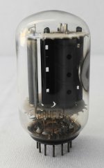
Just a note: the specimen I traced is a well used one, not new.
The EL503 is indeed quite powerful: two of it's three siblings look ok, no discoloration or anything, perfect getter, but somehow the metal strip connecting cathode to the base pin has melted away.
Like a fuse: just a little metal ball remaining at the stubs. Those cathodes can deliver serious current.
According to the datasheet, the EL503 is rated for 200 mA avg. DC. (only 1.05 Amp heater current) The melted wire is probably from an arc. Seems the guitar amplifiers were using the tubes well beyond their specs. If this tube were cheap and available, I could see experimenting with them, but $75 fuses don't much appeal to me.
If the OP is intrigued by frame grid power tubes, then there is the E130L for about half that price. It's got aligned frame grids for both grid1 and grid2, quite a remarkable design. May not be real robust against big audio peaks however. Some g1-k diode limiting called for to avoid grid1 current I think.
For just a cheap tube to experiment with, with all the latest technical design features and robust capabilities, the TV Sweep 21LG6A has got very nice plate curves in pentode, but only average triode curves and a low screen V spec. It's a typical gm optimized beam power pentode. 22KV6A is another similar one. Most any TV Sweep will give excellent high quality triode curves using the UnSET scheme however.
Not much around for power triodes at experimental type prices except the TV Vertical twin triodes. 6EM7, 6EA7, 6FM7, 6GF7, 6EW7 etc.
6FJ7 and 6DN7 have higher Mu, which can be used in UnSET mode to get high quality triode curves by lowering the Mu. UnSET will also increase the tube's peak power rating some.
Last edited:
... the TV Vertical twin triodes. 6EM7, 6EA7, 6FM7, 6GF7, 6EW7 etc.....
I suspect the 6EM7 and 6EA7 are not twin triodes but dual dissimilar triodes.
Which is often better because one triode may be a big beast and the other a tiny peanut. More power per bottle than any common twin triode.
Indeed, I goofed on that.
All of those I listed are dual dissimilar triodes, with one side around 10 Watt dissipation rated. Usually the smaller triode side can be used as a driver conveniently.
Oh, another tube that makes a pretty good 15 Watt triode is the 38HE7 Beam pentode/damper diode. On many (but not all) 38HE7 tubes, one can run just the pentode alone by putting 21V Htr (0.45 Amp) on pins 10 and 12. That drops out about 10 Watts of heat from the bottle, so the pentode can be uprated to 15 Watt readily (a big plate). Were on the famous $1 list once. ( have seen them in quantity for $0.35 ) Use UnSET with it and you can equal the 45.
pics: 38HE7 (triode mode)
Attachments
Last edited:
Thanks for the EL503 triode curves, I believe that they haven't been published anywhere until now.
To get a rough extimate for a design, my reference was the 8417 triode curve because the two tubes have some similarities, but the EL503 real curves shows a higher mu
The EL503 is basically the same as the 8417 except it's considerably smaller & comes from Philips instead of Westinghouse-Sylvania.
Westinghouse revised the spec, and the curves published are highly dependent on service conditions so are not accurate
Philips blew it with this valve, too little and too late, hence why such a nice device got stuck into guitar amps.
The 8417 contrary to belief is very tough and reliable so long as you feed it with a low impedance source.
The Mu is nigh on identical EL503/520 compared with 8417 but they upped the peak currents so the thing can run lower voltages with lower impedance transformer primaries.
Such a thing is impossible to remake and total unobtanium like the 8417 is fast becoming.
Again to prevent oscillation and runaway you need low impedance drive, and great care wiring, which is why ALL successful quads of them use low value anode resistors to prevent them rocketing off into RF stratosphere...
If you want to reinvent the same valve you need to be thinking of swapping in a quad of 7591 which is basically HALF a 8417 and are now cheap in repro form.
A matched quad of 7591 makes 100W as Bogen amply proved, with their diminutive PA amps using quad of 7868 - same valve as 7591, smaller package, which is even smaller than the EL503 and a lot more reliable.
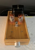
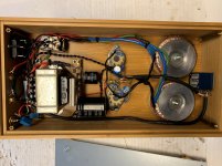
Testing the triode wired EL503 on a single ended setup has been surprisingly quick and easy. This amplifier is obviously not meant to be "done right" on a tecnical standpoint. As smoking-amp noticed on post #8, a conventional build with this tube does have no sense today. My goal was to build a fun amplifier with the parts I already had, exploiting the EL503 peculiarities: high mu, high cathode emission with only 1A filament draw, and 27W anode dissipation on a glass envelope about the same size of a 6V6GT. Triode curve shape suggests that 3K or maybe 5K anode load would give less distortion and better sound quality than the datasheet value of 1200 ohms, but it was not the case on my tests with a 6 ohms speaker. A 230v to 16V 20VA toroidal power transformer outperformed a much bigger 40W 250mA Toroidy Hi-Fi single ended transformer with 3K primary. This is my subjective evaluation, I have not done a measurement. I also tried several toroidal power transformers before settling for this one; most of them had a severely limited bandwith. To avoid saturation of the ungapped output transformer and to keep the tube cold to extend life, I selected a quite unconventional 150V 50mA working point. Mu is so high that if sub-watt performance is enough (headphone amplifier, desktop computer speakers), or if a high-output preamplifier is available, the EL503 can run as SPUD amplifier without preamplifier tube. I have 86dB speakers so I added a E88CC gain stage. This also enables the addition of global feedback, if desired. Power supply is very simple: the cheapest 20VA 6.3V filament transformer from the RS components catalog, and a standard small 55+55V control transformer to get 150V DC at 100mA. A insulation transformer would work just fine. I fitted on this amplifier two matched but worn EL503s that have 80% emission and almost no getter left. It sounds surprisingly well. The 100 ohm dropping resistor on the CRC power supply filter could be increased in value and dissipation if a 100dB+/1m speaker is connected. With my speakers, I barely hear a extremely faint hum at 1cm from the woofer.
Attachments
- Home
- Amplifiers
- Tubes / Valves
- New DIY Amp based on EL503/EL520