I have built a KT-120 tube amp and have been trying to get a simple and effective standby so the tubes can warm up a bit before blasting them with 500V. My first implementation was a switch between the first and second filter caps after the full wave rectifier (5AU4 with series diodes between the AC and the plates), but 2 of the switches have shorted closed. My next try was to switch the center tap of the power transformer to ground. Lower potential, I have seen it mentioned before as a standby method. My problem with that is I still have 514V at the filter cap open or closed. Closing the switch causes current to flow and sound but my meager understanding of theory suggests I should have no or little voltage after the rectifiers with the switch open. Instead I have 650v potential between G1 and P, that can't be good. Can you help me to understand why this is happening before I move on to the MOSFET switch for the B+? Or should I just go there now?
Presumably the bias supply is providing the charging path. The voltage should sag down a lot as the tubes warm up.
Why? That's what the tubes were designed for.I have 650v potential between G1 and P, that can't be good.
Last edited:
The simple answer is "you don't need one".I have built a KT-120 tube amp and have been trying to get a simple and effective standby
The only case the standby circuit is useful is when your bias supply comes to the proper voltage slower than both the B+ voltage and the heaters' temperature.
Look this, post 14..
" In valves, if it is rectified with silicon diodes, the plate voltage appears instantly, then the delay would be appropriate, in cases where the rectification is valve, the plate voltage will appear in an increasing way according to the gradual increase of emission of the filament of the rectifier, this gives time to the heating of the power valves, let's say in other words, that voltage and current increase gradually until reaching the regime values, in these cases I consider the delay not necessary.- "
Sistema de proteccion para parlantes con amplificadores a valvulas. | Foros de Electronica
In addition to the above, in a tube amplifier, - I think I remember - that what will shorten its life, - in addition to use - will be when the filament material wears out and is finally cut.
So obviously the valve will stop working.
The plate will not be bothered much by the sudden high voltage, given its physical construction and that it attracts electrons, only when the filament heats the cathode, but it is not an instantaneous closed circuit like that of the filaments.
They are only my two cents, but experts will answer you here, 6A3 among them, have a little patience, these are difficult times .....
Merlinb, if you are the man responsible for the Valve Wizard website - thank you very much, its been very informative to this valve newbie.
One thing I did spot, is that the the Mu Follower page seems to be missing from the left hand links listing.
The Valve Wizard -Mu Follower
I noticed that you aren't keen on standby switching, does this include soft starting of the HT?
The Valve Wizard
I am in the process of a parellel KT120 SE amp (probably a bit ambitious for a newbie!) and wasn't intending any standby/soft start feature.
My thinking is that if the HT is applied, the warming up of the heater fulfills this function.
Last edited:
Last edited:
The best "standby" that also is best for tube life is to turn down volume to zero.I have built a KT-120 tube amp and have been trying to get a simple and effective standby so the tubes can warm up a bit before blasting them with 500V. My first implementation was a switch between the first and second filter caps after the full wave rectifier (5AU4 with series diodes between the AC and the plates), but 2 of the switches have shorted closed. My next try was to switch the center tap of the power transformer to ground. Lower potential, I have seen it mentioned before as a standby method. My problem with that is I still have 514V at the filter cap open or closed. Closing the switch causes current to flow and sound but my meager understanding of theory suggests I should have no or little voltage after the rectifiers with the switch open. Instead I have 650v potential between G1 and P, that can't be good. Can you help me to understand why this is happening before I move on to the MOSFET switch for the B+? Or should I just go there now?
Tubes has no problem with instant B+, but as you have a tube rectifier your B+ caps will have a gradual voltage buildup.
In short - don't bother with standby or delay.
Replacing the tube was exactly my thinking of wanting a delay or standby circuit. The 5AU4 is a natural delay, a SS rectifier is immediate. I am being convinced however it may not be necessary. What prompted this was a sudden and dramatic failure of one KT88 previously used. It shorted G1-K and rivalled Chernobyl in intensity along with the 5AU4. I replaced them with KT120 thinking a little extra reliability may occur.
I needed to add a standby switch because I use AZ1 mesh rectifiers which spark if they're not warmed up when the HT comes on.
I have a separate transformer for the rectifier and for the HT. So I just added a switch in the mains input to the HT transformer. Pretty simple and it works.
I have a separate transformer for the rectifier and for the HT. So I just added a switch in the mains input to the HT transformer. Pretty simple and it works.
One solution to large transient inrush currents is to use Choke input filters.
But you have to select the correct power transformer when doing the original design.
Secondary Volts x 1.414 = cap input filter's max DC volts out.
There are additional voltage drops from the rectifier, and transformer primary and secondary DCRs
Secondary Volts x 0.9 = choke input filter's max DC volts out (when loaded).
Much lower transient current, lower harmonic structure (less high frequency harmonics), lower chance of hum that is caused by B+ ground loops.
There are additional voltage drops from the rectifier, transformer primary and secondary DCRs, and the choke DCR.
Tradeoffs of a Choke input filter:
Need higher secondary volts
Need a choke (heavy)
Need a choke (expensive)
Need a choke (more space)
Magnetic spray from the choke
Try it next time. Take care of the selection of the choke, angular rotation, distance to output transformers, and enjoy how it works.
(and do not use magnetic steel chassis . . . hum).
Last edited:
6A3 Summer, I see you've answered the call, thank you for that.
I learn together while trying to help the OP....")
Tell me what you think of the following that I had written before seeing your post :
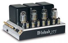
Modern tube amplifiers use Schottky diodes, they have their advantages and disadvantages compared to conventional diodes, but I think that if MC Intosh - in their updated version of the MC275 - stopped using vacuum tubes in the PS, they must have a good reason. ....
McIntosh MC275 power amplifier | Stereophile.com
Oh the reviewers! Sometimes I wonder if they are not guilty of so much snake oil, but I am surprised that I never saw an MC275 with its protection cage on, a friend bought one of these and left the cage inside the packing box....
" (When listening, I removed the cage, in part because I liked watching the tubes glow, and in part because, in my experience, cages of this sort usually vibrate. First, however, I received assurances from McIntosh that the cage was entirely for safety purposes, and that removing it wouldn't harm the sound.) "
I learn together while trying to help the OP....
Tell me what you think of the following that I had written before seeing your post :
Modern tube amplifiers use Schottky diodes, they have their advantages and disadvantages compared to conventional diodes, but I think that if MC Intosh - in their updated version of the MC275 - stopped using vacuum tubes in the PS, they must have a good reason. ....
McIntosh MC275 power amplifier | Stereophile.com
Oh the reviewers! Sometimes I wonder if they are not guilty of so much snake oil, but I am surprised that I never saw an MC275 with its protection cage on, a friend bought one of these and left the cage inside the packing box....
" (When listening, I removed the cage, in part because I liked watching the tubes glow, and in part because, in my experience, cages of this sort usually vibrate. First, however, I received assurances from McIntosh that the cage was entirely for safety purposes, and that removing it wouldn't harm the sound.) "
Attachments
Last edited:
They may have removed the rectifier tubes for many reasons.
But here is one to consider . . . If I start from scratch, I can use a power transformer with less B+ secondary turns, the tube rectifier has perhaps 30 to 60 Volts drop, almost no drop in a solid state rectifier.
And, there is no 5V rectifier filament(s) to power either, so one or two less filament secondaries.
A slightly less expensive power transformer, and less heat from the transformer, and less heat from the now 'missing' rectifier tubes.
How about a stiffer B+ voltage, because of solid state diodes.
How about the quality of rectifiers tubes back then, and the quality of rectifier tubes now?
What about the price of a good rectifier tube?
How about more air space on the same chassis size, if there are no rectifier tubes?
I probably did not think of all the reasons that they might have made that decision, but someone else can add their thoughts about that.
This will solve your issues:
Linear Audio High-voltage Delay for Tube Amplifiers V4 – diyAudio Store
Handles up to 500V B+, user-set delay between 20secs and 255 secs.
Small enough to be tucked away in the amp.
Can be installed without changes to the existing supply.
Best thing since sliced bread ;-)
Jan
Linear Audio High-voltage Delay for Tube Amplifiers V4 – diyAudio Store
Handles up to 500V B+, user-set delay between 20secs and 255 secs.
Small enough to be tucked away in the amp.
Can be installed without changes to the existing supply.
Best thing since sliced bread ;-)
Jan
"...I think that if McIntosh - in their updated version of the MC275 - stopped using vacuum tubes in the PS, they must have a good reason..."
The 275 never used tube rectifiers, neither in the old nor new version. McIntosh used tube rectifiers only in their mono models, such as MC-30 and MC-60, but not the stereo models like 275 and 240 and 225.
my simple delay start
I use 6C33C power tubes. I read that their life will be extended if the B+ comes on at least 2 mins after the filament power. So I simply put 2 power switches. One powers the entire amp, the second just the power to the B+ transformer primary. So, flip the main switch on, wait at least 2 mins and then the B+ switch. Easy. I also let the amps warm up before playing music. I am getting very good reliability with these tubes that are notorious for early and frequent failure.
I use 6C33C power tubes. I read that their life will be extended if the B+ comes on at least 2 mins after the filament power. So I simply put 2 power switches. One powers the entire amp, the second just the power to the B+ transformer primary. So, flip the main switch on, wait at least 2 mins and then the B+ switch. Easy. I also let the amps warm up before playing music. I am getting very good reliability with these tubes that are notorious for early and frequent failure.
The 275 never used tube rectifiers, neither in the old nor new version. McIntosh used tube rectifiers only in their mono models, such as MC-30 and MC-60, but not the stereo models like 275 and 240 and 225.
Good to know, thanks.
Have you seen any with the protection cage? I could not find a photo on the web ...
I use 6C33C power tubes. I read that their life will be extended if the B+ comes on at least 2 mins after the filament power. So I simply put 2 power switches. One powers the entire amp, the second just the power to the B+ transformer primary. So, flip the main switch on, wait at least 2 mins and then the B+ switch. Easy. I also let the amps warm up before playing music. I am getting very good reliability with these tubes that are notorious for early and frequent failure.
I read about that solution, but frankly, I have my doubts. There you do not speak of a gradual and increasing current of filament, which I repeat, for me, is the main cause of failure of the tubes.
My Prima Luna amp has a turn-on delay, and it works perfectly since I bought it, (fingers crossed here) but these guys don't provide circuits to know what's "under the hood".
Things are getting more and more complicated for electronics fans, unfortunately .....
- Status
- This old topic is closed. If you want to reopen this topic, contact a moderator using the "Report Post" button.
- Home
- Amplifiers
- Tubes / Valves
- Standby circuit for tube amp