Hi all,
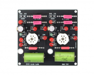
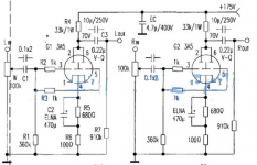
I'm looking for a little advice on the implementation of a cheap 3a5 board commonly available on Aliexpress. The pics below show the board which I guess many of you have seen, and I've included the schematic as well. I've hooked it up on the output of a DAC, and it performs "fine" but as you'd expect there is hum etc.
Not having any experience with DHT valves, in particular, I'd like some advice on heater wiring. So you can wire the heater in parallel or series, either 1.4/2.8V and 110/220mA current draw. There is cathode bias on this board, so I can't see how I can do what others advise in some other 3a5 threads, and connect the DC 1.4v across pins 1+7 and 4 and connect one end to ground. Obviously I'm missing something here, but having read around a bit I'm not any wiser!!
Is it as simple as leaving the heater supply floating? Any other advice to play with this thing?
Many thanks in advance for any help.
Attachments
I have a very basic LM2596 module pressed into service with an inductor and cap on the output (as per the datasheet). Its not the quietest supply I'm sure, but gives the 1.4V and given that the current is low its not pushed too hard.
I suppose my question though is more about what way to wire the filaments - either go with series or parallel and floating or grounded. If grounded, then where to ground.
I suppose my question though is more about what way to wire the filaments - either go with series or parallel and floating or grounded. If grounded, then where to ground.
@astouffer - sorry I misread your question there.
No, I don't mean wiring both tubes in series - I mean within a single tube. So, you can bring one side of the 1.4V supply to pin 4 (ie above the cathode resistor) and the other side to pins 1+7.... or you can bring 2.8V to pins 1 and 7. In either case you are kinda floating the supply I suppose.
Then do the same thing on the other tube.
-fran, I have built 3a5 pre as transformer (parafeed) output with 2.5x gain. It gives me excellent SQ, better than any of the half a dozen pre I tried earlier. In my opinion you need extremely good PS for anode and filament supply. And yes you need separate winding for each filament.
According to the attached schematic the PCB is configured for series filament (for each tube) so you need 2.8 volt supply not 1.4 volt. Supply will be floating.
Regards
According to the attached schematic the PCB is configured for series filament (for each tube) so you need 2.8 volt supply not 1.4 volt. Supply will be floating.
Regards
@minhaj - yes, and I know in this case I have a fairly basic CLCRC B+ supply, and the filament supply is also basic. I might try pressing a LT3045 into use for the filament, it should have pretty good noise rejection, and can handle the current I think.
So when I wire up the existing filament supply, and leave it floating I get quite a bit of buzz - all of the voltages etc work out as per the schematic which is reassuring. Another suggestion I saw was to take out the cathode bias and put some LEDs in there instead - aiming for a forward voltage matching the stock circuit.
The advice so far is really helpful - thank you all very much.
thank you -fran. For current capability please check LT3045 data sheet. I use voltage reg +current reg for filament supply and only then it works.
For best operating points please check: Filament Bias: a practical example with 3A5 DHT – Bartola(R) Valves
I request you to show some respect to the battery DHT and go slow and steady with them. Forget about using LED etc. Your ebay PCB and 175 volt supply will not give you optimal op plus gain will be too high for modern amps.
Regards
Regards
So I did some more experiments. I had only 1 x LT3042 reg so I did one channel with that, and another with the LM2596 switcher. The switcher channel was much noisier. So the LT3042 type regs could work well.
@minhaj - your post gave me another idea. I took 4 D-cells I had here, hooked them up with a switch and used them. Its silent as the grave")
So despite hating messing with batteries and charging them etc, I think the easiest solution here is just that - we'll see how long they last. They were made for batteries, and maybe everything else is just shoehorning a solution where it don't fit so easy.
Fran
@minhaj - your post gave me another idea. I took 4 D-cells I had here, hooked them up with a switch and used them. Its silent as the grave
So despite hating messing with batteries and charging them etc, I think the easiest solution here is just that - we'll see how long they last. They were made for batteries, and maybe everything else is just shoehorning a solution where it don't fit so easy.
Fran
Member
Joined 2009
Paid Member
I know its obvious in a way, but this is a viable solution. I think if I set up a carrier to hold the batteries and a decent switch setup, then its very useable. I could probably set up a switching job that would switch between heaters and a battery charger.
Thanks to all for your help, its much appreciated.
Thanks to all for your help, its much appreciated.
I'm not sure of the cathode voltage by the schematic, but it is possible to use the filaments themselves to obtain the bias by connecting the negative end of the cells and the filament common to ground; and the positive end of the cells to one of the filament pins. You will need an individual cell for each triode in the tube, however. If you were cascading the triodes, you could even stack the filaments to get 1.2V on one triode and 2.4V on the second, assuming you were using rechargeables
Thanks Sheldon - good to hear from one of the gurus of the 3a5!Your name pops up all the time in the searches!
Thinking of the batteries still - what is the max heater voltage you think the 3a5 can take? I'm wondering about rechargeables, and even D-cells, tend to be around 1.5-1.6V, which means the tube sees a little over voltage.
Thinking of the batteries still - what is the max heater voltage you think the 3a5 can take? I'm wondering about rechargeables, and even D-cells, tend to be around 1.5-1.6V, which means the tube sees a little over voltage.
''what is the max heater voltage you think the 3a5 can take?"
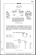
You always should check data sheet for spec. If data sheet not available then yes you may ask people for this.
D-cell is always 1.5 volt but if you measure it unloaded you will get 1.6volt+. Rechargeable AA battery is always 1.2 volt.
Regards
You always should check data sheet for spec. If data sheet not available then yes you may ask people for this.
D-cell is always 1.5 volt but if you measure it unloaded you will get 1.6volt+. Rechargeable AA battery is always 1.2 volt.
Regards
@minhaj - I understand your point, yes, the datasheet is widely available, but I was asking more for personal experience. For example something along the lines of "I use them all the time with LiFePO4 batteries which are charged to 3.5V with no apparent issues".... or the opposite as the case may be. The datasheet says 1.4 or 2.8V with no other tolerance mentioned.
As a further example, I have seen it written a few times that these valves function very well on starved filament supplies (mimicking a discharged battery) - again this is not mentioned anywhere on a datasheet.
As a further example, I have seen it written a few times that these valves function very well on starved filament supplies (mimicking a discharged battery) - again this is not mentioned anywhere on a datasheet.
I think you should stick with data sheet spec for now.
@minhaj - always good advice - thank you for your input. I'm just searching about for solutions which make the battery system a bit more user-friendly. I will spend some time this evening with the thread @sheldon linked to above as well. The more I read, hopefully the more I understand.
- Home
- Amplifiers
- Tubes / Valves
- 3a5 output stage advice