I was demoing some new-to-me speakers (8 ohm, not a difficult load) and was using my Dynaco ST-35. It was playing fine for awhile (10min?) and then the music stopped and I heard a hum and I turned off the amp. Smelled a little smoky smell.
I took out the amp, opened it up, inspected inside and couldn't see anything particularly wrong. So I put some dummy loads on the speaker outputs and turned it back on upside down so I could see if anything obvious was happening.
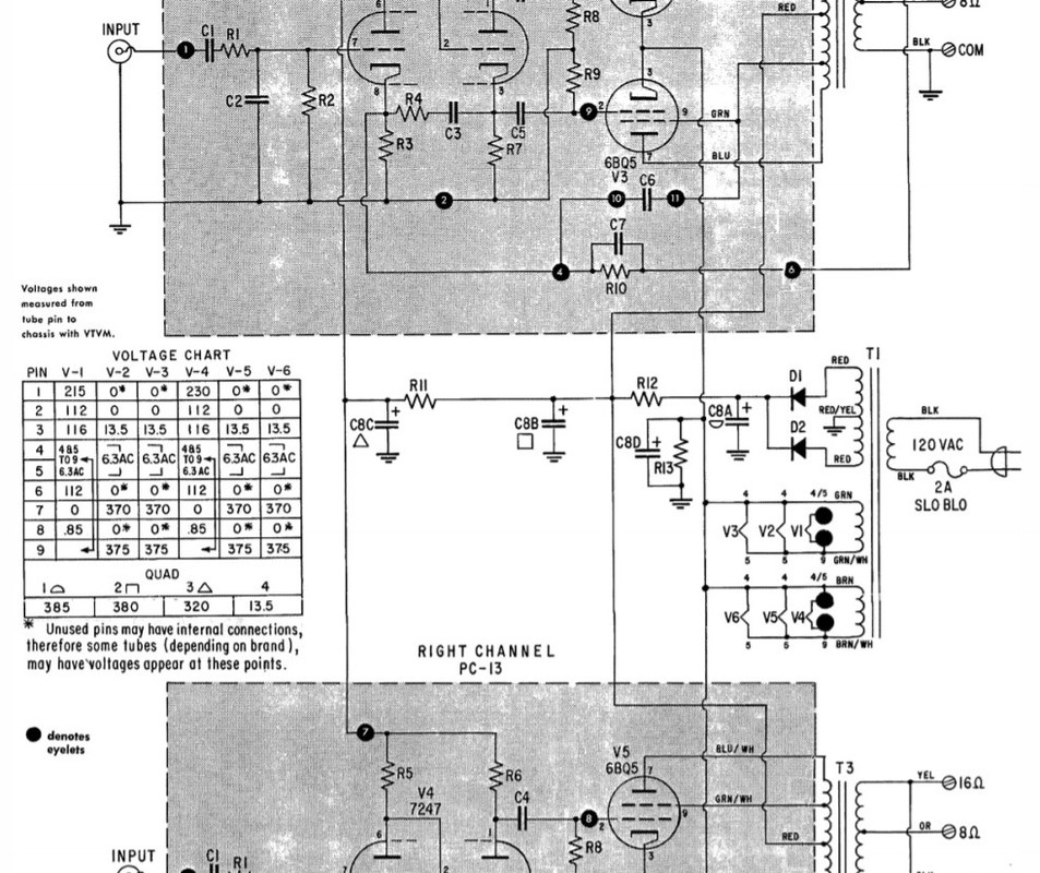
Turns out the 50ohm/5W (R12 in schematic) started smoking, so I quickly turned it off.
I measured the main power supply capacitances C8A, C8B, C8C, C8D. C8C and C8D measured as the implemented parts indicated. C8A and C8B measured significantly higher than expected. C8A should have been 40-60uF but measured about 160uF. C8B should have been 20-40uF but measured more like 260uF.
Came back a few hours later, and now C8A and C8B are both measuring about 80-90uF (still higher than expected, but lower than immediately after I powered down the amp).
Any idea why R12 would start smoking - I mean there must be very high current flow through there, but C8B wasn't shorted to ground or anything.
Haven't tested the tubes, output, or power transformers, but everything was working for 10min or so.
Just looking for suggestions on where I might start looking for problems given the symptoms.
Thanks.
I took out the amp, opened it up, inspected inside and couldn't see anything particularly wrong. So I put some dummy loads on the speaker outputs and turned it back on upside down so I could see if anything obvious was happening.
Turns out the 50ohm/5W (R12 in schematic) started smoking, so I quickly turned it off.
I measured the main power supply capacitances C8A, C8B, C8C, C8D. C8C and C8D measured as the implemented parts indicated. C8A and C8B measured significantly higher than expected. C8A should have been 40-60uF but measured about 160uF. C8B should have been 20-40uF but measured more like 260uF.
Came back a few hours later, and now C8A and C8B are both measuring about 80-90uF (still higher than expected, but lower than immediately after I powered down the amp).
Any idea why R12 would start smoking - I mean there must be very high current flow through there, but C8B wasn't shorted to ground or anything.
Haven't tested the tubes, output, or power transformers, but everything was working for 10min or so.
Just looking for suggestions on where I might start looking for problems given the symptoms.
Thanks.
If your C8 is the half century old original, that's a place to start. The common cathode resistor for all of the output valves tends towards letting a somewhat gassy valve run away, sometimes catastrophically. These old gals are very solid, and with good capacitors are going to live forever. Sound just fine, too.
YOS,
Chris
YOS,
Chris
C8 isn’t original, as it’s only a 2 cap can cap, but it may be an older cap. The label from it is here:
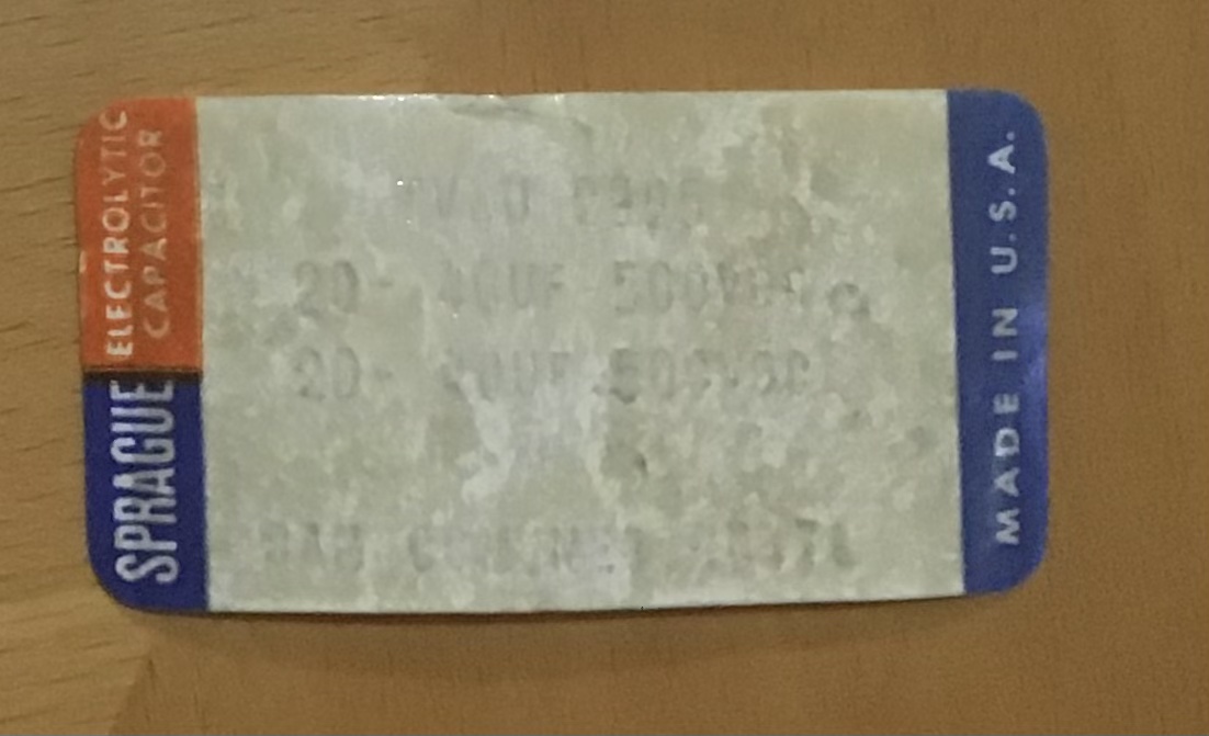
I don’t know whether the label roughly dates the cap. It’s hard to read, but it says 20-40uF for both elements of the can.
The first cap of the can cap is used for C8A, but since the spec is 60uF in schematic, the previous owner paralleled a 20uF cap with that under chassis to get 40-60uF. The second 20-40uF cap of the can cap is used by itself for C8B (spec 40uF in schematic). C8C and C8D are both under chassis discrete caps.
My cap meter is a simple one measuring capacitance only, no ESR or any other cap specs. But as mentioned in the first post, C8A and C8B are measuring above the schematic value.
Maybe I do away with the can cap entirely and install all new under chassis caps to match the schematic.
I’m thinking I should probably test the tubes as well as I installed all new tubes before firing up the amp. They’re new production Mullard reissues that appeared to be a measured and matched unused quad. That is the one variable that changed. I had previously been using vintage tubes, but not carefully matched w.r.t. brand or strength. Since I had the new matched quad sitting around, I thought I’d put those in before demoing the new speakers. I suppose it’s possible I have a bad tube and should rule that out.
Can this amp be safely powered up without tubes? I’m thinking maybe just to measure some voltages (which I know may be a bit higher w/o tubes) and see whether the 50ohm/5W resistor still is problematic without power tubes installed.
Electrolytic caps are a maintenance item; like beloved pets, you'll bury a few. Gotta let them go. I can recommend HayseedHamfest.
Yes, you can safely run that amp without the output valves. B+ will be higher, so C8 will be stressed, but only as much as it is on ordinary start-up. If you have a Variac you can experiment as you will.
If this machine is new to you, I'd give it new electrolytic caps, new coupling caps, and someday a modification to separate cathode resistors and bypass caps for the output valves. But that's not critical with new matched valves.
YOS,
Chris
I'll vote for replacing the caps (install an EFB board is my recommendation , see Daves Store: Dynaco SCA-35 ST-35 EFB Upgrades and Restoration)
And do read the analysis of st-35 before destroying the circuit, lots of misunderstanding exists.
And do read the analysis of st-35 before destroying the circuit, lots of misunderstanding exists.
I’ll try it without the tubes today. This unit was gifted to me by a friend and he worked on it from original. I’m not sure, but those may be repro driver boards.
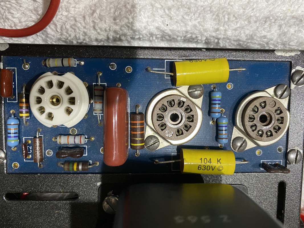
And a couple of undershot pics:
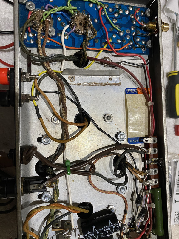
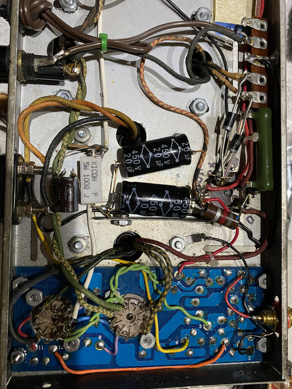
I did snip the 20uF cap from C8A if you look in the pic. It was reading so much higher than the schematic’s 60uF that I wanted to isolate the can cap’s contribution from the 20uF axial cap. The axial cap read at 20uF so it was the can cap reading the high value, on C8B as well (2nd element of can).
Will report back after trying it sans tubes.
If the 50ohm resistor still smokes without tubes, I guess I should get take the can cap out of the circuit and use discrete caps underneath.
Well, will report back first before making any mods.
And a couple of undershot pics:
I did snip the 20uF cap from C8A if you look in the pic. It was reading so much higher than the schematic’s 60uF that I wanted to isolate the can cap’s contribution from the 20uF axial cap. The axial cap read at 20uF so it was the can cap reading the high value, on C8B as well (2nd element of can).
Will report back after trying it sans tubes.
If the 50ohm resistor still smokes without tubes, I guess I should get take the can cap out of the circuit and use discrete caps underneath.
Well, will report back first before making any mods.
This is reproduction boards.
It seems likely that the electrolytic cap is the culprit.
Instead of hunting expensive and not exactly right fit caps i warmly recommend a EFB board. It will replace all caps with modern board mounted caps and in addition add EFB which lowers dist and reduces the powertubes load. At about the same cost as non-fitting electrolytic caps.
This is reproduction boards.
It seems likely that the electrolytic cap is the culprit.
Instead of hunting expensive and not exactly right fit caps i warmly recommend a EFB board. It will replace all caps with modern board mounted caps and in addition add EFB which lowers dist and reduces the powertubes load. At about the same cost as non-fitting electrolytic caps.
Thanks, I’m going to do just that. Not just to resolve the current issue, but just as much for the advantages of improved design. Sent a request for invoice just now.
Thanks, I’m going to do just that. Not just to resolve the current issue, but just as much for the advantages of improved design. Sent a request for invoice just now.
Just for anyone who stumbles across this thread and is wondering about cost, it's about $90 USD for the EFB board and all the components that are required to implement it. I received the board and just ordered the parts, so it'll be another couple of weeks before I can install it.
$90 Yuk! Four Panasonic or Nichicon radial lead 450 vdc electrolytic caps are about $12. >3000 hours service life rated. The two cinch type solder strips to mount them on about $2. A little roll of 600 v wire. Plus two boxes of freight, newark & digikey don't sell the solder terminal strips. guitar amp houses & surplus houses do. Plus a box of #6 x 1/2" SS screws and elastic stop nuts so they don't come unscrewed.
Those "Made in USA" caps had to be 30 years old. Oxygen attacks the rubber seal whether turned on or sitting on the shelf. Capacitance is not the critical measurement of an old e-cap, ESR & leakage current are. Your smoking resistor pretty much put the nail in the coffin on too much leakage current.
I had to replace the e-caps in my dynakit ST70 4 times. That is not the worst, my H182 organ had 187 e-caps. Was putting out about 2 watts when I bought it with no percussion & "string bass" (pedal sustain). Works great now, will rattle the chandelier in the room. No new tubes required.
$90 Yuk! Four Panasonic or Nichicon radial lead 450 vdc electrolytic caps are about $12. >3000 hours service life rated. The two cinch type solder strips to mount them on about $2. A little roll of 600 v wire. Plus two boxes of freight, newark & digikey don't sell the solder terminal strips. guitar amp houses & surplus houses do. Plus a box of #6 x 1/2" SS screws and elastic stop nuts so they don't come unscrewed.
Those "Made in USA" caps had to be 30 years old. Oxygen attacks the rubber seal whether turned on or sitting on the shelf. Capacitance is not the critical measurement of an old e-cap, ESR & leakage current are. Your smoking resistor pretty much put the nail in the coffin on too much leakage current.
I had to replace the e-caps in my dynakit ST70 4 times. That is not the worst, my H182 organ had 187 e-caps. Was putting out about 2 watts when I bought it with no percussion & "string bass" (pedal sustain). Works great now, will rattle the chandelier in the room. No new tubes required.
The EFB board shipped was $37 and the rest was component cost via Digikey (about $7 of which was shipping). In the board, you’re really buying the design and compensating for the time/knowledge invested, which I have no problem with. And I ended up paying $6.xx for 100 screws when I only needed a 10% of that, but I preferred that to making a drive to a HW store and hunting for the right parts to save $5.
True that I didn’t realize it would come out to be that much based on the comment that it wasn’t much more than getting the caps and doing it discretely. But I was gifted the amp, and the advantages of the EFB over stock are worth it for me, so I’m okay spending the $ and getting a really clean implementation with some power/other advantages. I plan to keep the amp long term.
Note: The EFB inventor Dave Gillespie recently posted a minor mod involving 4 diodes to prevent some corner case rare regulator failure scenarios, so anyone doing the EFB mod should look for that as it’s far easier to do the mod before the board is installed vs after it’s already installed.
Note: The EFB inventor Dave Gillespie recently posted a minor mod involving 4 diodes to prevent some corner case rare regulator failure scenarios, so anyone doing the EFB mod should look for that as it’s far easier to do the mod before the board is installed vs after it’s already installed.
I have these boards and shall appreciate a specific link to this “recent post” regarding the 4 diodes. I may have missed that.
Thanks,
Francois
I have these boards and shall appreciate a specific link to this “recent post” regarding the 4 diodes. I may have missed that.
Thanks,
Francois
Hello Francois,
Here it is:
Bullet Proofing The EFB Cathode Bias Regulator | Audiokarma Home Audio Stereo Discussion Forums
")
Hi All,
I'm back, unfortunately. . .
I implemented the EFB board, checked my work carefully, and I powered it on to bias the tubes.
The 50ohm/5W resistor immediately started smoking, so I powered it off right away. So same symptom as before replacing the can cap and under chassis discrete caps with the EFB board. The problem lies elsewhere apparently.
BTW, I never tried to powered it up again pre-EFB without the tubes. But anyway, it appears it wasn't the power supply capacitors.
Would a bad power or output transformer possibly create this symptom (smoking 50ohm/5W resistor)? Or am I looking for a faulty component on one of the PC13 boards?
Looking for suggestions on where to start with the caveat that I don't appear to be able to power this up for any length of time without smoking the resistor. Unless pulling the tubes gives me a shot at measuring some things without the resistor doing its thing.
Thanks.
Remove all the output transformer connections on both the primary and secondary side, Measure all the resistances on both sides of each transformer. On the secondary side (to the speakers) measure from the ground connection to the 8 ohm tap and the 16 ohm tap. Also measure each of the resistances to the transformer frame. Repeat this on the primary side. Measure from the B+ (center) feed wire to each plate wire and to each screen grid wire. Also measure from the B+ feed to the transformer frame. Although the secondary resistance will be low, in no case should any of these readings be "0", which would indicate a short. This will either find or eliminate the output transformers as the issue. If they are original Dynaco transformers, the resistances on the primary side from the B+ feed from one side (plate or screen grid lead of one tube) to the other will not be identical. That is normal, and is due to the way that they are wound.
Do you have access to a variac? It's is possible to run the amplifier with the output tubes removed, to determine which stage is drawing excess current, however, the B+ voltage will go high, depending on your AC line voltage.
Do you have access to a variac? It's is possible to run the amplifier with the output tubes removed, to determine which stage is drawing excess current, however, the B+ voltage will go high, depending on your AC line voltage.
Did you try with power tubes removed ? ( or all tubes if you like)
If it draws current you have a problem , maybe in the B+ cap(s)
Just tried it without any tubes. Yup, resistor still smokes.
All the caps in the EFB board are in the right polarity and they were ordered new from a reliable source (Digi-key).
The fact that the same resistor smokes pre-EFB and post-EFB would indicate the problem lies elsewhere, right?
- Status
- This old topic is closed. If you want to reopen this topic, contact a moderator using the "Report Post" button.
- Home
- Amplifiers
- Tubes / Valves
- Troubleshooting a Dynaco ST-35