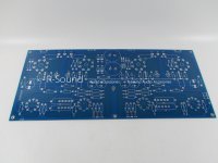
After a failed attempt of a cloned Maplin 4-20 amplifier I thought I would rescue the expensive components and try this Williamson design PCB.
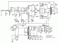
I won't get the schematics until the PCB arrives but it appears to use the 4 x octal sockets for the EL34 output tubes and B9A sockets for the pre-amp and phase splitter tubes.
I'm guessing these will be EF86 and ECC83.
My OPTs are Hammond 1650H.
I won't get the schematics until the PCB arrives but it appears to use the 4 x octal sockets for the EL34 output tubes and B9A sockets for the pre-amp and phase splitter tubes.
I'm guessing these will be EF86 and ECC83.
My OPTs are Hammond 1650H.
Attachments

That schematic has no global NFB. That’s not going to oscillate unless you do something really stupid in the power supply to make unintentional feedback (the only mechanism left). All this bickering we’ve been doing applies only when global feed back is used.
Triode-wired outputs often sound very good and have sufficient damping without any global feedback. Is your board wire this way, and does it have any feedback from the secondary of the OPT to the cathode of the input tube?
Triode-wired outputs often sound very good and have sufficient damping without any global feedback. Is your board wire this way, and does it have any feedback from the secondary of the OPT to the cathode of the input tube?
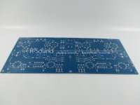

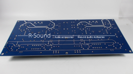
Yes Tom, those photos are of the same board.
Running the finals in UL, and both gain stages are low mu. There’s got to t be less than 10dB of feedback, lessening the chances of an instability. You may find it linear enough with the global feedback disconnected (and want the extra gain). Many of these amps that have instabilities use pentode mode outputs and high mu or even pentode front ends. Lots of open loop gain, and hence the stability problems.
Might be OK for testing but the HT will droop with current changes on the PP if it goes into class B. May also cause LF instability. You would be better with the correct transformer.
I don't think U1 is an EF86 looking at the PCB.
Looks more like this:
View attachment 929018
On the HV supply, is ok to use 100uF / 10H / 100uF. Then, lighten up on the preamp caps...20 uF work just fine. Also, the first preamp rail resistor in the wrong place...
This is probably closer to the actual schematic.
I'll have to wait until the actual schematic arrives and then source some ECC82's.
WOW....big design flaws......bias wiper does absolutely nothing here...
-g
Last edited:
It does its got a few volts across it and is dissipating a watt or two. Is got all the cathode current flowing through it. I guess in those days big trimmers were common. We would not do that today. The first rail resistor can come from the HT rather than the second rail depends on the filtering and HT you need. A LC filter is a good idea.
Last edited:
- Home
- Amplifiers
- Tubes / Valves
- Building a Williamson EL34 amplifier