Single Ended KT88 with 50% efficiency. Wow!....
How did you calculate to get 50% ?
The values in the schematic show approximately 55 watts plate dissipation.
His abacus is sticky. Or he read his sliderule in haste.
KT88 may be rated 35W or 42W. 18.6W/35W is 53%. 18.6W/42W is 44.3%.
55W is beyond the limit in any datasheet I know. If that IS the condition, then 18.6W/55W is 33.8%, which is entirely reasonable, even low.
Hi, as I was saying on page 2, I've been mislead by LTSpice considering the plate dissipation. I've used the standard procedure Alt+Click on the component and then Ctrl+Click on the plot to get the average value, but for some reasons it is not correct.
Please also consider that the EL34 and KT88 schematics are my adaptations, while the original design is with EL84.
I consider it an interesting design, but this can be because I'm not an EE and I'm a total newbie in Hi-Fi design. On top of tube's plate dissipation, I've probably also exceeded the maximum ds voltage of the njfet with the EL34 and KT88 design, but that made me think about the possibility to use a tube in that position instead of the njfet, and make it an all tube SE amp.
An interesting circuit indeed.
With all tubes, and the JFET replaced by a tube, I think the input stage would look like a modified SRPP (modified by having the output tube plate connected directly to the SRPP top plate).
Seems like a form of negative feedback.
If the KT88 pulls down too much, it lowers the SRPP top plate voltage.
If the KT88 does not pull down enough, it raises the SRPP top plate voltage.
Changing the SRPP top plate voltage, should change the SRPP top cathode voltage in the same direction, therefore changing the KT88 control grid in the same direction.
Comments, anybody, please?
Thanks!
Last edited:
Broskie has covered the 12ax7/KT88 configuration, he calls it "super triode". The KT88 feeds back through the 12ax7 anode. The end result is a composite triode with the mu of the 12ax7 but with much higher gm. The KT88 can be replaced by a power mosfet with a suitable biasing arrangement. I have a PP amp based on this concept, does 40W at 0.4% THD with no global feedback. With 10 dB global feedback THD is 0.03% at 20W (measured, not simulated).
I did a few sims of the jfet driving the cathode of the triode, this is the configuration mostly seen on the japanese sites discussing this concept. But I ended up going the more conventional route driving the triode grid.
I did a few sims of the jfet driving the cathode of the triode, this is the configuration mostly seen on the japanese sites discussing this concept. But I ended up going the more conventional route driving the triode grid.
ArcticBrew,
I took him at his word, '36W dissipation'/'18W' output = 50% efficiancy.
That is why I said Wow!
Practical SE amplifiers can not get 50% efficiency on sine waves, only on square waves at full clipping (or on sine waves that are at full clipping, which is a square wave).
And until you mentioned it, I did not know that the actual dissipation was 55W.
55W dissipation not only lowers the efficiency, it drastically lowers the tube life.
I once saw a Beam Power TV Horizontal flyback tube that had a hot spot on the plate. That heat melted the glass envelope across from the hot spot, then a meniscus was formed, and finally the closest part of the meniscus was opened, air entered, and the tube finally died.
That was a Robust tube, until it became Busted.
"You can always violate the rules, until the rules violate you".
Last edited:
I see you went from fet cascode to SSRP*, you can stabilize the gain of a fet/tubecascode in two ways: CCS on top of the tube fixes the current. and a resistor from source to ground to set the overal gain.. perhaps split it up into a cap bypassed part and a non bypassed part.
* edit i didnt get much sleep
* edit i didnt get much sleep
Last edited:
The 2SK30 Selected 'A' version has an IDSS range of from 1.2mA to 3.0mA.
If you put 180V on the plate of a 12AX7, and used -1V bias, you would get very close to 1.8mA of plate current.
Would you reject that 12AX7 if you got 1.2mA?
Would you reject that 12AX7 if you got 3.0mA?
A good 12AX7 would never be that far off.
To be more fair, if you had 80V on the plate of a 12AX7, and 0V bias, the plate current would be very close to 1.8 mA.
Would you keep that tube, if it either only had 1.2mA, or if it had 3.0mA . . . probably you would put that tube in your tube museum or in the garbage can.
JFETs, even 'selected' ones are hard to design with, versus good triode tubes.
I once built a JFET Line amp. It had two 9V batteries in series for B+. I used matched Drain load resistors. I used matched self bias resistors, and bypass caps. There was a dual volume control from the RCA jacks to the JFET Gates. I used cap coupling out, with a resistor after the cap to charge it up, and remove the DC at the output. I very carefully selected JFETs that matched quite well (a long laborious process). It performed reasonably well.
I also hand selected a JFET to use as a current source in a cathode coupled phase inverter. That also worked quite well.
After that, I never used JFETs in any amplifier again.
Last edited:
...Practical SE amplifiers can not get 50% efficiency on sine waves, only on square waves at full clipping.....
Not sure what you are saying.
The ideal efficiency in class A (no cutoff) for SINE is 50%. This is because the "content" of a Sine is half the content of the Square which holds it.
Practical tubes rarely beat 50% because losses. I have seen a very early transistor amp plot figuring 48% efficiency but they sure tweaked to get that number.
On Square Wave the ideal efficiency is 100%. You get out all that you put in. Until you move back to a real world.
PRR,
You are correct.
A switcher can approach near 100% efficiency.
For a single ended amplifier, if everything is perfect except the output transformer:
Most of the output transformers I have seen have insertion losses of from 0.5dB to 1dB.
An output transformer with a 1 dB insertion loss:
12.5 Watts from the output tube = 10Watts from the transformer secondary.
It is really hard to get 50% efficiency.
Thank you tikiroo, can I ask you some more details?Broskie has covered the 12ax7/KT88 configuration, he calls it "super triode". The KT88 feeds back through the 12ax7 anode. The end result is a composite triode with the mu of the 12ax7 but with much higher gm. The KT88 can be replaced by a power mosfet with a suitable biasing arrangement. I have a PP amp based on this concept, does 40W at 0.4% THD with no global feedback. With 10 dB global feedback THD is 0.03% at 20W (measured, not simulated).
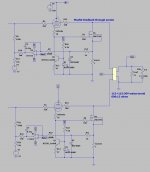
Here's my take on it...
The jfet/triode pair sort of looks like an SRPP, but it's not because the dc coupling to the KT88 means the load is very high. SRPP's are optimally designed for a particular load impedance. Here the triode acts more like an active load for the jfet. If the triode was connected to B+ it would act like a reasonably good ccs and the jfet gain would be very high. However the triode plate voltage is swinging due to being connected to the KT88 plate, so definitely not constant current anymore.
With more reasonable dissipation for the KT88, maximum power output is more like 13-14 watts @ 1.7% THD which is about 33% efficiency. Which is about normal for a SET (which is effectively what this is). Also note you burn 8-9W in the KT88 cathode resistor.
Looks like there is some distortion cancellation going on, I tried the supertriode configuration that Broskie describes (where the triode is running at constant current) with worse results. So I don’t know if you will get any better by changing the input stage. Although the 12ax7 is running at 390V which is well over the maximum rating of 300V.
Attached is the output stage of the PP amp I mentioned earlier. The mosfets feed back through the screens of the ECL85 pentodes (doing it that way instead of just triode strapping the ECL85 lets the mosfet drain voltage swing lower). ECL85's are loaded by CCS on the cathodes (BC550 and LED). The opamps are there as an autobias for the mosfets, the schottky diodes clip the source resistor voltage to allow the autobias to work into class AB.
This is driven by a folded cascode LTP phase splitter utilising the triode halves of the ECL85.
This is driven by a folded cascode LTP phase splitter utilising the triode halves of the ECL85.
Attachments
Thanks tikiroo, I will double check the EL34 version too, where voltages are lower.
So a better option could be to choose a different power tube like the EL509, that works better with low voltages and low loads.
Will it be possible an all tube SRPP, taking into account that we need to keep the power tube grid voltage quite low?
So a better option could be to choose a different power tube like the EL509, that works better with low voltages and low loads.
Will it be possible an all tube SRPP, taking into account that we need to keep the power tube grid voltage quite low?
...It is really hard to get 50% efficiency.
Technically on the sharp edge of impossible.
There are many cheats. Non-zero THD can put you over. Curvature and bias rectification can make full output more than twice *idle* dissipation (because you can cheat current into rising with signal). That's how original 6L6 at 19W Pdiss had a 10 Watt spec on early sheets. IIRC a 6550 sheet went further with 15% current rise and 13% THD.
The 48% efficiency was Bell Labs, who don't cheat, but had time to optimize. They also had no large fear of THD, and 300cps transformers can have much lower midband loss than our 50Hz iron.
- Status
- This old topic is closed. If you want to reopen this topic, contact a moderator using the "Report Post" button.
- Home
- Amplifiers
- Tubes / Valves
- Another hybrid design, this time SE