Spent a good deal of time listening to the amplifier last night and it sounds really good.
I have changed out the PT from a 250-0-250 to a 275-0-275 to get my B+ up to about 330 from 300. It probably wants to go a bit higher. Also put a film bypass cap across the first 47uf C in my CLC supply. The amp is VERY quiet. I also subbed a "Clarity cap" for the orange drop coupling capacitor eariler. I am not sure that made any difference at all. But it seems upping the B+ did.
I have changed out the PT from a 250-0-250 to a 275-0-275 to get my B+ up to about 330 from 300. It probably wants to go a bit higher. Also put a film bypass cap across the first 47uf C in my CLC supply. The amp is VERY quiet. I also subbed a "Clarity cap" for the orange drop coupling capacitor eariler. I am not sure that made any difference at all. But it seems upping the B+ did.
I've never used any of the so called 'Botique' devices. When I started out there really weren't any with perhaps the exception of the first class OPTs made by Partridge & used in The Williamson Amplifier. So at that time all I built was with what was used in ordinary manufacturing. With care I got good results.
More recently many of my projects were purpose built, many to be published. So I continued to use 'off the shelf', the kind of thing an ordinary person could easily find. If the builder wanted to try something else that would be OK & they often did.
Authoring an article for publication is very different than writing an engineering report or preparing a sales proposal. So need to be careful not to offend the people who've bought space to sell their products in the magazine. And since the readers are paying for the magazine they want to be both informed & entertained. But a very good experience, NTL.
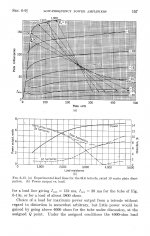
The attachment covering distortion is typical of all common pentodes & beam tubes. Your SE 6L6 OPT load should be down around 3K. Do you have a copy of the original paper I could read?
More recently many of my projects were purpose built, many to be published. So I continued to use 'off the shelf', the kind of thing an ordinary person could easily find. If the builder wanted to try something else that would be OK & they often did.
Authoring an article for publication is very different than writing an engineering report or preparing a sales proposal. So need to be careful not to offend the people who've bought space to sell their products in the magazine. And since the readers are paying for the magazine they want to be both informed & entertained. But a very good experience, NTL.
The attachment covering distortion is typical of all common pentodes & beam tubes. Your SE 6L6 OPT load should be down around 3K. Do you have a copy of the original paper I could read?
Attachments
The design is Alex Kitec's RH807. I think the links to this project are dead.
This is the thread that got me started down this path
Make an amp from Dad's tube stash
This is the thread that got me started down this path
Make an amp from Dad's tube stash
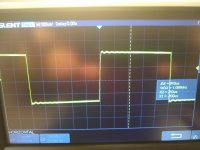
That looks to be very good. Can the scope export files to a PC thru a USB connexion?")
If the screen of the 6L6 is still running thru the unbypassed 10K resister there will be quite a bit of movement at that point. That is degeneration. And subtracts from the power capability of your amplifier. 99.44 % of users hate that!
If the screen of the 6L6 is still running thru the unbypassed 10K resister there will be quite a bit of movement at that point. That is degeneration. And subtracts from the power capability of your amplifier. 99.44 % of users hate that!
More Distortion Information
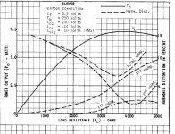
On the 6L6WGB Plot the D% curve is moving up & to the right on the RHS as load impedance is increased. Not a good sign for using a 6K OPT.
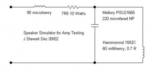
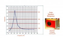
Many amplifiers are stable on the spec'd resistive load. But could have problems driving a speaker, a complex load. So many experimenters put together simple complex loads for testing. That way no one has to listen to a speaker during the test. Mine is shewn here attached.
A real speaker with impedance plotted to below the resonance. This is in a simple sealed enclosure, 3/4 inch plywood. The speaker is an auto replacement. Real cheap, I built two for the garage. Driven by a low cost SS AM/FM thing, 3W per channel. It competes with Skil Saws, Drills & so on.
Simple FB pairs such as your amp are seldom unstable. I've used 20 db NFB on ccts using replacement grade OPTs.
I dug into some of the old threads but was not able to discover why Alex Kitec put an unbypassed 10K in series with the screen. Or how the 6K OPT was selected. All still a mystery!
On the 6L6WGB Plot the D% curve is moving up & to the right on the RHS as load impedance is increased. Not a good sign for using a 6K OPT.
Many amplifiers are stable on the spec'd resistive load. But could have problems driving a speaker, a complex load. So many experimenters put together simple complex loads for testing. That way no one has to listen to a speaker during the test. Mine is shewn here attached.
A real speaker with impedance plotted to below the resonance. This is in a simple sealed enclosure, 3/4 inch plywood. The speaker is an auto replacement. Real cheap, I built two for the garage. Driven by a low cost SS AM/FM thing, 3W per channel. It competes with Skil Saws, Drills & so on.
Simple FB pairs such as your amp are seldom unstable. I've used 20 db NFB on ccts using replacement grade OPTs.
I dug into some of the old threads but was not able to discover why Alex Kitec put an unbypassed 10K in series with the screen. Or how the 6K OPT was selected. All still a mystery!
Attachments
White Noise sounds like a good idea.
But difficult to get objective tests with limited equipment. At a minimum you would need an 8W, 10W resister to hang on the amp output while you run your tests. Sounds like you are using a laptop based audio generator? How did you test to get the 6W reading?
But difficult to get objective tests with limited equipment. At a minimum you would need an 8W, 10W resister to hang on the amp output while you run your tests. Sounds like you are using a laptop based audio generator? How did you test to get the 6W reading?
I was going to test using a real bookshelf speaker.
Prior to this I was using a 8W dummy load on the outputs, input driven with a signal generator.
I measured the 6W by turning up the amplitude until I saw clipping on the scope. Then did ohms law. Matches pretty well with rough classA guidelines:
0.055A x 310V (plate voltage) x 0.4 = ~6.82W
Prior to this I was using a 8W dummy load on the outputs, input driven with a signal generator.
I measured the 6W by turning up the amplitude until I saw clipping on the scope. Then did ohms law. Matches pretty well with rough classA guidelines:
0.055A x 310V (plate voltage) x 0.4 = ~6.82W
- Status
- This old topic is closed. If you want to reopen this topic, contact a moderator using the "Report Post" button.
- Home
- Amplifiers
- Tubes / Valves
- Schade P2P and gNFB in RH807