I think that an un-bypassed 10k resistor resistor from B+ to the screen of a 6L6, when the 6L6 is operating in Beam Power Mode, causes the following:
1. Degeneration
2. Less maximum output power
3. Lower distortion at low and moderate power due to the degeneration
4. Lower plate resistance, rp, due to the degeneration
5. Much lower screen current when the plate voltage 'swings' all the way down to 50V.
6. The classical curves of power, load impedance, THD, 2nd, and 3rd Harmonic distortion curves are changed, because of the degeneration
Your comments to the above will be appreciated.
More food for thought:
Connecting the screen to a Ultra Linear tap, is degeneration too.
An un-bypassed 10k screen resistor in Beam Power Mode, and Ultra Linear Mode may have a few things in common, or at least be similar.
Last edited:
That is what was thinking in an earlier post, that an unbiased screen resistor is something in-between pentode mode and UL mode. Either the best or the worst of both those worlds.
I am not sure the power reduction is that significant, 40% of plate dissipation (par for a class A output I think) is about 6.8W for my operating point. I am measuring 6W .
I am not sure the power reduction is that significant, 40% of plate dissipation (par for a class A output I think) is about 6.8W for my operating point. I am measuring 6W .
Each section of a power amplifier has its problems, tradeoffs, etc.
Fix the power supply before proceeding to use it in a single ended amplifier (and the same goes for using it in a push pull amplifier, only more so because of the widely varying current demands versus widely varying signal output level).
I hate to be so political, but Real Art and Real Science works.
Beg to differ with you, but a PP, Class A amp is about the least varying load possible. Either instantaneously, or on average( any time period ).
Build a solid PS anyway...

cheers,
Douglas
Bandersnatch,
You are absolutely correct.
Yes, a Class A push pull tube amplifier has a very constant B+ load, even more so than a single ended amp.
But, "All Generalizations Have Exceptions" . . .
A large portion of Class A push pull tube amplifiers will go into Class AB before they clip.
That does not provide a constant load on B+.
Just sayin'
Bandersnatch,
You are absolutely correct.
Yes, a Class A push pull tube amplifier has a very constant B+ load, even more so than a single ended amp.
But, "All Generalizations Have Exceptions" . . .
A large portion of Class A push pull tube amplifiers will go into Class AB before they clip.
That does not provide a constant load on B+.
Just sayin'
Then they are not Class A. Period. It really can't get much simpler. If at their rated output, they cut one off, they are not class A.
cheers,
Douglas

Common Cathode Pentode/Beam Power Stage, with an un-bypassed large resistance screen resistor:
As g1 grid volts goes up (less negative),
The screen current goes up,
The g2 screen volts goes down,
If the screen volts goes down enough,
The plate current goes down,
So . . . the plate volts goes up.
That is description of the order of what may happen.
Good, or a Mess; I leave that to whoever wants to try it, under different values of un-bypassed resistors to g2 screen.
Last edited:
But no data to check what is happening. jderimig has a scope & other test equipment, why are there no test results comparing with & without the cap?
GE already wrote the report. Lots and lots of them. RCA too...
cheers,
Douglas
But no data to check what is happening. jderimig has a scope & other test equipment, why are there no test results comparing with & without the cap?
What tests and what signals should I use to compare bypassed screen versus unbypassed? Currently the unbypassed config looks as good as it can probably get on a scope with sine and square waves. Do I look at:
- Output power ?
- FFT ?
- Response with a reactive dummy load?
Make a list of the amp parameters that should be checked. Go thru the tests with G2 unbypassed, then again with the screen bypassed. A comparison can then be made, which of these conditions worked better.
Things to check on a first pass might include power at clipping on a Sine Wave, D% at One Watt, D% at 5W. Check the signal on the screen grid, how large is it. That can be applied to the published screen curves of the tube, something worth a look. Check square wave performance at say One watt, both on a load resister & into a speaker. Square wave at 100, 1000, & 10000 Hz.
Think your scope can record all these resulting waveforms & dumped to a PC for further analysis. Keep a record so you're not getting all this mixed up.
In real design the circuit would be made as distortion free as possible before any NFB. In the finished amplifier many problems are disguised by the NFB & how it is applied. For example on this amp, D% would be reduced by the loop FB whereas PS hum is accentuated by Schade.
What kind of signal generator are you using?
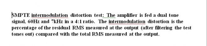
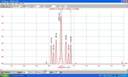
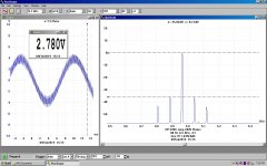
Your signal generator has many useful functions. It appears able to generate two waveforms simultaneously. so that intermodulation tests are possible with the FFT in your scope. One of the attachments below describes the SMPTE method, Society of Motion Picture & Television Engineers. Two frequencies, one LF the other HF are applied to the amplifier & the resulting intermods measured.
The historic method of obtaining the LF signal was to simply use a tap off the PT 6.3V winding, so 50 or 60 Hz. The HF signal, typically 7 KHz was synthesized by the analyzer. I use two analogue SGs, I've three of them. Your SG will provide both signals.
In some of my more recent tests I've used 80 Hz as the LF signal, that allows PS hum (120 Hz) to appear separate from the intermods.
The traces are for two different amplifiers, both PP triode with no NFB.
Attachments
- Status
- This old topic is closed. If you want to reopen this topic, contact a moderator using the "Report Post" button.
- Home
- Amplifiers
- Tubes / Valves
- Schade P2P and gNFB in RH807