datasheets are pretty comprehensive.
Andy.
Most tube data sheets strike me as like the pirates' code "they just guidelines".
I see most people treat these tube data sheets as if a tube were a solid state device, and they are not........
=I want to update the spec on the EZ-81.
Change the max input cap from 40 uF, to 100 uF.
Just for a start.....
You could put an alternative data-sheet in circulation that shows operating conditions with higher capacitance, but you would also have to up the minimum series resistance requirement to keep it within permissible current spikes. But then again, most designers of tube equipment don't read data-sheets
 Otherwise rectifiers would last forever and that cuts into their margins.
The flip-side of the coin is that these permissible maximums are there for a reason, and 40uF is too much considering modern SMPS optimized electrolytics are harder on the tube anyway cause of lower ESL and ESR.
Whats the point in putting 100uF and overloading the tube during the start up? In push pull most of the ripple is cancelled in the OPT anyway.
You could put an alternative data-sheet in circulation that shows operating conditions with higher capacitance, but you would also have to up the minimum series resistance requirement to keep it within permissible current spikes. But then again, most designers of tube equipment don't read data-sheets
The flip-side of the coin is that these permissible maximums are there for a reason, and 40uF is too much considering modern SMPS optimized electrolytics are harder on the tube anyway cause of lower ESL and ESR.
Whats the point in putting 100uF and overloading the tube during the start up? In push pull most of the ripple is cancelled in the OPT anyway.
You are joking ?
1. designers follow the spec like it come down from the hand of God.
2. the reason, when this spec was first published, the biggest paper cap , in them days, was about's in the 40 uF range. The electrolytes did not appear until the late 1950's.
3. push-pull has nothing to do with it.
4. It takes the EZ-81 about 10 seconds to warm up, and you saying "current spikes" and lower Effective Series Resistance ?
5. one point being ; inside surface amplifier ; it uses a dual 100uf cap with 10 henry choke ; as a pi filter for the B+. Just using what parts that could be had for a plate supply......
Last edited:
Somtimes..
1. Those specs are there for a reason, just because it doesn't blow up on the spot doesn't mean ignoring the design specifications is sound engineering. I just Simulated the EZ81 in PSUD2 and increasing C1 in size from 40 to 100u does have the effect of increasing the number of mains cycles the cathode is required to provide excessive current.
2. I have prewar (1939) Radios in my collection that have paper aluminium electrlytic capacitors in them filled with Boric Acid. Nasty stuff to replace. Your timetable is off by a couple decades. Here in the Netherlands they are called "mushroom capacitors" by collectors due to their crimped on top. and have been in use since the early 30's il see if i can find some whit date codes.
3. Yes it does, push pull amplifiers will tolerate 10's of volts of peak to peak ripple on the electrolytic feeding the output transformer with no discernable noise on the output. For Single ended however you need a much cleaner supply.
4. Yes, if you read the data sheet you would have seen that they specify a minimum series resistance measured from the center tap to each anode of the tube. This is to limit the current through each section of the rectifier. If you violate this specification there is a good chance nothing will happen, but dont act surprised when your super special GEC 5R4GY starts arcing because you put 100 instead of 4uF before the choke and didn't bother to read up on the plate to plate series resistance.
5. I don't know that particular amp, so i really cannot comment.
Oh and to answer your original question, if the current manufacturers feel that their cathodes can withstand higher peak currents than the old production stuff im sure they would have advertised this by now, fact of the matter is that cathode formulations are more or less the same in current production runs as in NOS tubes. Just because there is not a marked nor R&D money to put something better in tubes. Currently there is no one administering or updating any old data sheets, Or any central authority like you have whit 2Nxxx transistors (JEDEC?)
If you looked at any datasheets you would have seen Philips (The parent company of mullard) stopped revising them around C 1968.
Last edited:
I am wondering, who would it be, for me to talk to, to update some of these spec's in tube data sheets...?
I'll pass on your recommendations. How about a sample schematic of one of your amps that use parts beyond spec? What are typical MTBFs? And which parts fail first?
no parts have failed.
this is the amp.... is a prototype , built for my own personal use..
as you can see , on top of the white box , the ez-81, the 500v dual 100uf cap, and the 10 henry choke.
Surface 3 Full Build - YouTube
still does not answer my question.
this is the amp.... is a prototype , built for my own personal use..
as you can see , on top of the white box , the ez-81, the 500v dual 100uf cap, and the 10 henry choke.
Surface 3 Full Build - YouTube
still does not answer my question.
Some rock guitarists follow the route of extreme design. And back it up with boxes of spare tubes while on the road. Ypu could consult with them, perhaps exchange some ideas.
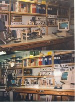
But I like the wine jug in the photo. Did it contain some of California's best?
Think I will pass on your advice anyway. My workshop about 10 yrs ago, a laptop now replaces an old CRT thing, All hooked up to some test equipment, I gave away my 2-channel, 100 MHz scope several years ago.
But I like the wine jug in the photo. Did it contain some of California's best?
Think I will pass on your advice anyway. My workshop about 10 yrs ago, a laptop now replaces an old CRT thing, All hooked up to some test equipment, I gave away my 2-channel, 100 MHz scope several years ago.
Attachments
I am wondering, who would it be, for me to talk to, to update some of these spec's in tube data sheets...?
Very funny.
You don't need to talk to anyone. Just publish your own data sheets. If you can convince people that your data is more accurate and/or complete than the manufacturer's, they'll use yours.
Seriously?? You probably need to contact a psychic who can perform a seance. The engineers who designed the tubes and came up with these specs are long dead. And they didn't just pull the data sheet specs out of a hat. They are the result of extensive testing.I am wondering, who would it be, for me to talk to, to update some of these spec's in tube data sheets...?
You apparently haven't looked at the data sheets very closely. You might want to read the whole thing before claiming that you know more about how to operate a particular tube than the engineers who designed them.I want to update the spec on the EZ-81.
Change the max input cap from 40 uF, to 100 uF.
Just for a start.....
For one thing the EZ81 data sheets list the cap size as 50uf, not 40uf.
Can you use a 100uf input cap instead? Maybe.
If you had read the complete data sheet you would have seen that the basic data is followed by a series of charts and an explanation of how to use them. The charts are essentially a 3 part test. You need to take actual measurements of your amp, do the calculations and plug it into the charts. If your amp passes all 3 tests, your cap value is acceptable.
Here's the GE data for the 6CA4 which is equivalent to an EZ81.
https://tube-data.com/sheets/093/6/6CA4.pdf
Oh, and you're absolutely wrong about designers always sticking closely to the specs. Many of the low cost Chinese amps use first caps that are way to high. I know this from reading numerous posts from owners whose rectifier tubes have failed repeatedly until they replaced the cap.
IMO, there is not really any advantage in pushing the limits of the first cap. I prefer to put minimal stress on the rectifier. If you're using a CLC or CRC supply it's easy enough to use the standard value for the first cap and increase the value of the second cap, which can be much larger if you like. If you compare the two configurations in PSUD2 you probably won't see a huge difference.
OP reminds me of myself about 6-7 years ago, its an attitude thing. I wouldn't be surprised if we were on the same spectrum Which has nothing to do with physics.
Anyway, there are valid reasons for these design maximums, once you take the time to dive further into them you will see.
Lifes a lot easier if you accept the other sides argument, i had to learn that on multiple occasions the hard way. But i guess wisdom comes with age.
Which has nothing to do with physics.Anyway, there are valid reasons for these design maximums, once you take the time to dive further into them you will see.
Lifes a lot easier if you accept the other sides argument, i had to learn that on multiple occasions the hard way. But i guess wisdom comes with age.
1. i already did deep dive , when i was young ET in the Navy, 45 years ago.
2. last few days, i put a 1000uF load on ez-81, feeding a 500 ma load. it still not complaining.....not near as much as you people ,, ,, , ,. . . . . .
3. unless of course, all of this data gets uploaded onto the Valve Wizard website, and i see him getting credit for all my work ; again...
2. last few days, i put a 1000uF load on ez-81, feeding a 500 ma load. it still not complaining.....not near as much as you people ,, ,, , ,. . . . . .
3. unless of course, all of this data gets uploaded onto the Valve Wizard website, and i see him getting credit for all my work ; again...
Last edited:
Yeah the tube wont blow up with a 100-1000uF with a cold start but you can do the same with a switch and apply AC at the plates with the filament on....
You can burn the transformer also, but no one listen to the advises, not even the old ones, the values listed in the datasheets are conservatory to all kinds of uses and applications meaning some guy had years trying to explode a tube with all the means posible to use that info to redact a datasheet, for manufacturing/consumer issues regarding quality and burned houses and appliances........
You can burn the transformer also, but no one listen to the advises, not even the old ones, the values listed in the datasheets are conservatory to all kinds of uses and applications meaning some guy had years trying to explode a tube with all the means posible to use that info to redact a datasheet, for manufacturing/consumer issues regarding quality and burned houses and appliances........
.... and you can prove all this ?meaning some guy had years trying to explode a tube with all the means possible to use that info to redact a datasheet, for manufacturing/consumer issues regarding quality and burned houses and appliances........
Well, I have a test rig running on my bench, even now as we speak, and
I'm not hearing the tube complaining....
Again, the tube is not solid state. The tube is a mechanical device, and I just don't think it cares................
I think the data sheets are written more as application notes, rather than absolute max limits....
If I had the time, I would really burn this tube up, but I don't, and as mentioned before, I not get anything for it........
-g
Last edited:
- Status
- This old topic is closed. If you want to reopen this topic, contact a moderator using the "Report Post" button.
- Home
- Amplifiers
- Tubes / Valves
- Data Sheets