Hi,
I'm trying to build something, its a voltage amplifier using a high gm pentode connect as triode.
If I have a cathode resistance of 10 ohm, and I bypass it with 0.01uf, does that capacitance serve to shunt hf noise to ground, or does it 'boost' hf of the stage.
thanks,sam
I'm trying to build something, its a voltage amplifier using a high gm pentode connect as triode.
If I have a cathode resistance of 10 ohm, and I bypass it with 0.01uf, does that capacitance serve to shunt hf noise to ground, or does it 'boost' hf of the stage.
thanks,sam
Any resistance (impedance) in the cathode for a common cathode amplifier stage will reduce the gain of the stage. Bypassing the 10 ohm resistor will lower the impedance above circa 1.6MHz, so there would be an increase in gain above 1.6MHz - but at that high a frequency there are so many other gain changing issues to worry about.
Maybe you meant to use 10k, and so the RC corner frequency would then be 1.6kHz ?
Maybe you meant to use 10k, and so the RC corner frequency would then be 1.6kHz ?
Have a read of this simply put comment on cathode bypass capacitors-
The Cathode Bypass Capacitor Explained - AUDIO WORKSHOP
The Cathode Bypass Capacitor Explained - AUDIO WORKSHOP
Any resistance (impedance) in the cathode for a common cathode amplifier stage will reduce the gain of the stage. Bypassing the 10 ohm resistor will lower the impedance above circa 1.6MHz, so there would be an increase in gain above 1.6MHz - but at that high a frequency there are so many other gain changing issues to worry about.
Maybe you meant to use 10k, and so the RC corner frequency would then be 1.6kHz ?
Thanks,
Nup.. its 10R cathode resistor bypassed with 0.01uf.
What would that do?.. why is it there?
Do you have a schematic of the circuit you are looking at? Like all things - it depends on context.
Why have you chosen 10 ohm cathode resistor, or are you copying something?
Have you got the circuit built and powered and now testing, or is this just at schematic stage, or ..... ?
Why have you chosen 10 ohm cathode resistor, or are you copying something?
Have you got the circuit built and powered and now testing, or is this just at schematic stage, or ..... ?
If the resistor value is very low it is normally done to avoid noise in a first stage (phono stage) here also the offered signal is very small. No problem also with headroom etc.
The capacitor across the resistor is to compensate the roll-off of the tube in the top reageon as any resistor will act as local feedback and the C prevents this for the high frequencies.
The capacitor across the resistor is to compensate the roll-off of the tube in the top reageon as any resistor will act as local feedback and the C prevents this for the high frequencies.
Not sure either but could it be to compensate for the noise of the 10M resistor at the grid?
The 10M actually is determining the bias voltage on the grid as it is almost floating. But as this value is so high it will add noise. So adding a resistor (noise) in the cathode could somehow cancel it out (i doubt it) ? Unfortunately i never experimented with this setting.
The 10M actually is determining the bias voltage on the grid as it is almost floating. But as this value is so high it will add noise. So adding a resistor (noise) in the cathode could somehow cancel it out (i doubt it) ? Unfortunately i never experimented with this setting.
Do you have a schematic of the circuit you are looking at? Like all things - it depends on context.
Have you got the circuit built and powered and now testing, or is this just at schematic stage, or ..... ?
Thanks to all.
I'm at collecting the parts stage.
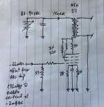
Please see below.
Attachments
Last edited:
Sorry, the 10 Ohms in the cathode of the Input tube, does not qualify as a bias resistor.
Instead, the 10Meg Ohm Rg, grid resistor provides Grid Leak Bias.
Most all of the bias is from Rg, not from Rk.
But then, I am not surprised that the designer of that OTL amp chose that. OTL has its own tradeoffs, even if it does not use grid leak bias.
Grid Leak Bias is real good for a Regenerative Radio Stage.
Grid Leak Bias in Audio Circuits is very inconsistent.
Just look at various threads for problems that Tubes/Valves, and Instruments & Amps have with Grid Leak Bias.
Re: Futterman, and grid leak bias.
Sample variations require selected tubes. 10R cathode resistance provides some degree against oscillation, low volt potential to measure plate current with negligible increase to drive impedance (blah).
Can we please get back on topic: the purpose of Ck in the attached schematic (scroll up to #11).
Thanks
Last edited:
Sam, the discussion about the use of 10R is pivotal to the reason for it being shunted.
If the 10R was a means for monitoring cathode (ie. anode) current, then the shunt cap may well be to suppress the influence of noise on the cathode current measurement process. Many monitoring schemes get messed up by noise - without better appreciation of the use of the 10R all one can say is that the RC corner frequency is 1.6MHz.
If the 10R was a means for monitoring cathode (ie. anode) current, then the shunt cap may well be to suppress the influence of noise on the cathode current measurement process. Many monitoring schemes get messed up by noise - without better appreciation of the use of the 10R all one can say is that the RC corner frequency is 1.6MHz.
- Status
- This old topic is closed. If you want to reopen this topic, contact a moderator using the "Report Post" button.
- Home
- Amplifiers
- Tubes / Valves
- Small value Ck (like really small)