I have a big dilema and trying to get some feedback from the forum here ")
While building a SE amp using 6L6GC (15W output transformer) I have a hard time do decide between 3 option for the driver based on 6SL7 dual triode:
- DC coupled cathode follower
- AC coupled cathode follower
- SRPP
I read some articles but would appreciate if you have any opinions about what option would be based with these tubes - 6SL7 + 6L6GC SE.
Thanks
Attachments
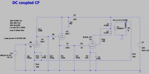
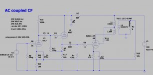
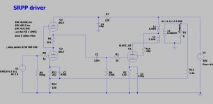
On all 3 circuits, depending on the DC cathode voltage of the 2nd 6SL7 triode, you may have to use a 2 resistor divider from B+ to ground, and a bypass cap across the resistor that goes to ground, so that you can elevate the 6SL7 filament.
The 6L6GC in UL mode has a fair amount of gain. And it has only a moderate Miller Effect capacitance, not as much as triode wired mode, but more than Beam Power mode.
It may be possible to drive the 6L6GC satisfactorily with one, or two 6SL7 triodes in parallel (using individual self bias resistors and individual bypass caps). The parallel plates can drive a single resistor plate load.
The parallel 6SL7 triode(s) in that configuration has a little 2nd harmonic distortion, but that 2nd harmonic distortion will be partly cancelled by the Ultra Linear 6L6GC tubes 2nd harmonic distortion, because they are out of phase (serial 2nd harmonic distortion cancellation).
And, using one or two triodes like that, will not require any elevation of the 6SL7 filaments.
. . . petertub +
I leave the comparative analysis of the rest of the circuits to those who have built 2 or 3 different types of those circuit topologies.
Last edited:
Thank you both - I wanted to use 2 6SL7 tubes, one for each channel. That is why I have 2 triodes (within one 6SL7) available for each channel and thought about a combo ACCF, DCCF or SRPP.
Do you think that parallel plate loaded triodes (with individual cathode biasing) will be a better option here?
Also I plan to use elevated fillament using resistor divider from B+ to GND for both 6SL7 and 6L6GC.
Do you think that parallel plate loaded triodes (with individual cathode biasing) will be a better option here?
Also I plan to use elevated fillament using resistor divider from B+ to GND for both 6SL7 and 6L6GC.
On all 3 circuits, depending on the DC cathode voltage of the 2nd 6SL7 triode, you may have to use a 2 resistor divider from B+ to ground, and a bypass cap across the resistor that goes to ground, so that you can elevate the 6SL7 filament.
The 6L6GC in UL mode has a fair amount of gain. And it has only a moderate Miller Effect capacitance, not as much as triode wired mode, but more than Beam Power mode.
It may be possible to drive the 6L6GC satisfactorily with one, or two 6SL7 triodes in parallel (using individual self bias resistors and individual bypass caps). The parallel plates can drive a single resistor plate load.
The parallel 6SL7 triode(s) in that configuration has a little 2nd harmonic distortion, but that 2nd harmonic distortion will be partly cancelled by the Ultra Linear 6L6GC tubes 2nd harmonic distortion, because they are out of phase (serial 2nd harmonic distortion cancellation).
And, using one or two triodes like that, will not require any elevation of the 6SL7 filaments.
. . . petertub +
I leave the comparative analysis of the rest of the circuits to those who have built 2 or 3 different types of those circuit topologies.
Ok, that is why I didn't want to leave one half of the dual 6SL7 unused. One more question - if I parallel 2 triodes with separate cathode resistors how to deal with the global NFB? As you can see in my circuit I planned to use a global NFB. Should I use two separate cathode resistors bypassed by caps, connect their lower ends together and then connect it through the singe small resistos to the ground. NFB will then go in between. Something like this? (attached)
Parallelling the triodes within one tube should be fine , with separate cathode resistors (R11 and R11') should be fine as long as the triodes are not to far from each other.
In fact much better then having an unused trode lingering.
Attachments
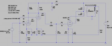
I see no picture but this seems to be what i had in mind. R14 between ground and the two R11 and R11-bis , NFB connects to the R14//R11-R11-bis) nodeOk, that is why I didn't want to leave one half of the dual 6SL7 unused. One more question - if I parallel 2 triodes with separate cathode resistors how to deal with the global NFB? As you can see in my circuit I planned to use a global NFB. Should I use two separate cathode resistors bypassed by caps, connect their lower ends together and then connect it through the singe small resistos to the ground. NFB will then go in between. Something like this? (attached)
The plate resistor R12 should be halfed too as it's shared with 2 triodes.
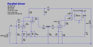
Your schematic in Post # 6 looks correct.
Separate grid stoppers
Separate RC self bias, 1k Ohm each
150k/2 two plate load
The right circuit parts for global negative feedback.
The parallel stage gives 1/2 the output impedance
2X the current to deliver to the 6L6GC rg1 and Miller Effect capacitance
Global negative feedback resistor, R15, may need a compensation capacitor across it, depending on the output transformer's phase gain / phase versus frequency.
Looks good.
Last edited:
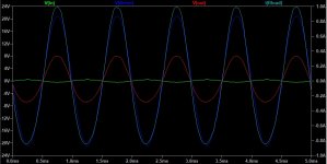
Thanks a lot 6A3sUMMER. I tried to modify the circuit based on your comments - see attached + simulated signals.
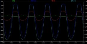
One more question - it seems to be ok based on the simulation with 0.4V input signal. However when I go higher with input voltage I see a clipping - se picture (0.6V input).
My output transforer allows 15W so what should I do to get more output from this circuit? Go higher with power supply? Eg from current 300V to 350V? Modify any resistors?
Your schematic in Post # 6 looks correct.
Separate grid stoppers
Separate RC self bias, 1k Ohm each
150k/2 two plate load
The right circuit parts for global negative feedback.
The parallel stage gives 1/2 the output impedance
2X the current to deliver to the 6L6GC rg1 and Miller Effect capacitance
Global negative feedback resistor, R15, may need a compensation capacitor across it, depending on the output transformer's phase gain / phase versus frequency.
Looks good.
Attachments
Be careful when making voltage measurements, you do not want to get shocked.
Measure the DC voltages on each of the 6SL7 cathodes, and on the parallel plates of the 6SL7.
Measure the DC voltages on the 6L6GC cathode, the plate, and the screen.
I am guessing that the DC volts on the 6SL7 cathodes is low.
Perhaps the 1k cathode resistors, and/or the 6SL7 plate resistors need to be adjusted.
Power the amp off.
Make sure that the B+ voltage goes to zero volts (you have to have bleeder resistors across the B+ cap or caps. It takes time for the voltage to discharge.
Ohmmeter readings:
Make sure that the output transformer is wired correctly, the B+ to the Plate should have the largest DCR, the DCR from the screen to the B+ should be about 40% of the plate to B+ DCR.
Measure from the 6SL7 grid to ground, and 6SL7 cathodes to ground.
Measure from the 6L6GC g1 to ground.
Check all resistors for correct value.
Report back the readings.
You have a 6L6GC single ended amplifier. The 15 Watt output transformers will not put out 15 Watts for that amplifier. When you get the amp up and running properly, that watt rating should provide for the power at low frequencies to not roll off too soon, nor distort too soon.
I forgot what transformers you have.
What are the primary impedance, inductance, mA current, and weight ratings?
What is the make and model number?
Last edited:
Actually I'm not that far now - I'm only designing the circuit now, trying to simulate it in LTSpice but no real HW built now.
I'm trying to have the initial schematic done before I start witing it. That is why I wanted to decide what to do with the dual triodes (cathode follower, SRPP or parallel them) and now I'm trying to understand what needs to change in the schematic if higher power is needed. My output SE transformers are large custom designed and should support 15W with low frequencies. My understanding was that they should support continuous 15W SE output.
I'm trying to have the initial schematic done before I start witing it. That is why I wanted to decide what to do with the dual triodes (cathode follower, SRPP or parallel them) and now I'm trying to understand what needs to change in the schematic if higher power is needed. My output SE transformers are large custom designed and should support 15W with low frequencies. My understanding was that they should support continuous 15W SE output.
Be careful when making voltage measurements, you do not want to get shocked.
Measure the DC voltages on each of the 6SL7 cathodes, and on the parallel plates of the 6SL7.
Measure the DC voltages on the 6L6GC cathode, the plate, and the screen.
I am guessing that the DC volts on the 6SL7 cathodes is low.
Perhaps the 1k cathode resistors, and/or the 6SL7 plate resistors need to be adjusted.
Power the amp off.
Make sure that the B+ voltage goes to zero volts (you have to have bleeder resistors across the B+ cap or caps. It takes time for the voltage to discharge.
Ohmmeter readings:
Make sure that the output transformer is wired correctly, the B+ to the Plate should have the largest DCR, the DCR from the screen to the B+ should be about 40% of the plate to B+ DCR.
Measure from the 6SL7 grid to ground, and 6SL7 cathodes to ground.
Measure from the 6L6GC g1 to ground.
Check all resistors for correct value.
Report back the readings.
You have a 6L6GC single ended amplifier. The 15 Watt output transformers will not put out 15 Watts for that amplifier. When you get the amp up and running properly, that watt rating should provide for the power at low frequencies to not roll off too soon, nor distort too soon.
I forgot what transformers you have.
What are the primary impedance, inductance, mA current, and weight ratings?
What is the make and model number?
Attachments
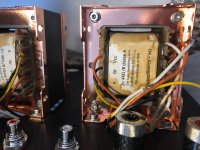
just to add - the output transformer is EI96 bobbin (large), primary 4k ohm, 26H, secondary output 8 ohm. Should be 15W continuous operation.
That is why I thought about 300V B+ and 48 mA cathode biasing. This should give me 15W output I believe.
But using these parameter in the simulation it seems the output is only 8V / 1A (peak) with 0.4V input signal. Increasing the input signal is making output clipping. That is why I'm think if it is an issue of the simulation or if I should modify something to be able to achieve higher output power.
You got aproximately the power that I would expect for 48mA (0.048A) and a 4000 Ohm load.
Prms = ((Ipeak)squared) x (R/2)
Prms = 0.048Asquared x (4000/2)
Prms = 4.6 Watts rms
Prms = ((Epeak) squared)/(2 x R)
Prms = 8 squared / 2 x 8
prms = 64 / 16 = 4 Watts rms
Peak voltage swing = Peak current x R
Peak voltage swing = 0.048A x 4000 Ohms = 192V peak.
If the signal is symetrical, that is 192V x 2 = 384V peak to peak.
I do not know what the cathode bias is, but you said you had 300V B+.
300V x 0.048A = 14.4 Watts, there is less than 14.4 watt dissipation total in the plate = the screen.
That is because you subtract the cathode bias from the 300V, and you subtract the voltage drop in the output transformer DCR from that too.
4 Watts / 14.4 Watts = 0.277. That is 27.7% efficiency. That is reasonable for a single ended amp.
An output transformer does not make power. It transforms the power that is delivered to it by the output tube, changing the impedance from the primary impedance to the output impedance.
Last edited:
Thanks 6A3sUMMER. So does this mean that I’m not able to get more than 4.6 W rms power in this configuration?
To summarize what I have:
- 6L6GC which is rated 20W+
- B+ 300, 330 or 350 V (3 taps power transformer)
- output transformer - see above 4k/8 ohm (EI96, should support output amp up to 15W rms)
How do I get more than 4.6W of the rms power? (With 300 V B+ and 48 mA bias). Higher B+ Or higher bias current?
- Status
- This old topic is closed. If you want to reopen this topic, contact a moderator using the "Report Post" button.
- Home
- Amplifiers
- Tubes / Valves
- ACCF vs DCCF vs SRPP driver for 6L6GC SE amp