Perhaps I could go with 47uF-100ohm-470uF? B+ would drop about 30 volts in this case.
CRC filter is a good idea. Keep the 470uF. The first cap could also be a 470uF but some think a lower value is better for sound quality. Keep an eye on the power rating of the resistor.
With the new B+ voltage, tube bias point may be ok.
Is the OT 3.95k a-a or just one side?
Last edited:
Thanks cnau! Good point about the bias after B+ change.
I am pretty sure it is 3.95k ohm a-a. I measured from "P1" to "P2" (each on opposite ends of the primary - I assume this means plate 1 and plate 2).
The only other taps are Sg1, Sg2, and B+ (screen grids and B+, obviously).
I am pretty sure it is 3.95k ohm a-a. I measured from "P1" to "P2" (each on opposite ends of the primary - I assume this means plate 1 and plate 2).
The only other taps are Sg1, Sg2, and B+ (screen grids and B+, obviously).
I am pretty sure it is 3.95k ohm a-a. I measured from "P1" to "P2"
Seems quite low. Maybe you measured using the 16 ohm tap? Which would mean the 8 ohm tap should be about 8k a-a; more reasonable for the way the amp is biased.
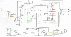
What is the function of C3 (green), and can I replace it with .22uF/600v ?
Link below has a good explanation of the DC coupled long tailed pair.
The Valve Wizard
Seems quite low. Maybe you measured using the 16 ohm tap? Which would mean the 8 ohm tap should be about 8k a-a; more reasonable for the way the amp is biased.
The amp only has 4 and 8 ohm secondaries, and I am positive I used the 8 ohm. I can double-check it, though.
Thanks for that link. I'll do some reading.
Shuguang i25 (AKA Psvane TS66) - In its stock form (P-P U/L + NFB) it was rated for 25W per channel.
It could indeed have a 4k Ra-a output transformer. This is from looking at Mullard EL34 operating conditions (1964).
Very interesting, indeed. I am looking at this - https://www.icp-electronique.com/images/Image/dossier_pdf/EL34 MULLARD.pdf
By the looks of it, when configured in distributed load w/43% Sg taps (ultralinear) topology, the ideal Ra-a is 6k. This amp was originally configured in UL mode, but with Ra-a 4k.
However, in a later section it clearly shows that in P-P triode mode (g2 connected to a, g3 connected to k -- which is exactly how I have mine wired) with Rk bypassed, at 430V B+ (which is damned close to my 426V) I need 440ohm Rk (for each tube, bypassed) and 5k Ra-a is ideal.
So my 4k Ra-a should be "fine"? Should I adjust the Rk value to compensate for the 1k discrepancy? Does that even make any sense?
Either way, triode seems like a better use of these 4k OPTs in this amp (vs. distributed load).
One other thing that is interesting in that PDF is that removing the bypass cap on the Rk doubles the ideal Ra-a to 10k. This sacrifices 5 watts of power but the distortion figure plummets by a factor of 4.
This stuff is pretty fun.
Last edited:
A while back I played around with a p2p EL34 PP amp and I was amazed at the range of sound signatures you could get out of it by changing topologies and operating conditions (and no doubt some of my setups just sounded bad because of inexperience!). Learned a lot.
The operating conditions given on the Mullard PDF you attached I believe are only there to give you a range of possibilities. The unbypassed EL34 with a 10k OT will give very low distortion if that is what you are looking for.
If you haven't already I suggest learning about selecting tube operating conditions. I am a fan of the Valve Wizard:
The Valve Wizard
In your case running a 6 ohm speaker on the 4 ohm tap will give you 6k Ra-a on the tube which is ok for a bypassed EL34 triode running at your operating points. Should give you low distortion especially since you are using feedback.
... or a 12ohm speaker on the 8 ohm tap, and my main speakers just happen to be ~12 ohms.
The interest in the unbypassed EL34 configuration was merely academic. The fact that removing the bypass cap requires doubling the OPT primary impedance raised my eyebrows. The reason why is not yet obvious to me. Thanks for the link.
The interest in the unbypassed EL34 configuration was merely academic. The fact that removing the bypass cap requires doubling the OPT primary impedance raised my eyebrows. The reason why is not yet obvious to me. Thanks for the link.
Last edited:
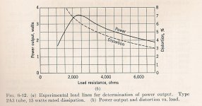
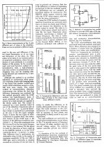
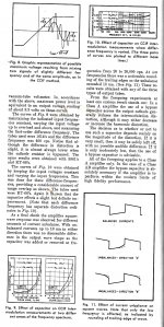
Triodes are very tolerant to the load impedance. But if load goes too low D% increases rapidly. Refer to the 2A3 distortion plot, the curve is typical of all triodes. Ideally the load should at a minimum 2X the plate resistance rp of the tube. So for PP that would be 4X. Good design usually goes farther, that way D% can be reduced without too much loss of power.
Refer to p8 of the Philips spec sheet for a PP EL34 triode connected example running on a 400V supply.
")
Attachments
Hi John,
The Phillips PDF shows 5K ohm, just like the Mullard PDF does on page 3 https://www.icp-electronique.com/images/Image/dossier_pdf/EL34 MULLARD.pdf (plots on p.18)
I'd like to see a power/distortion vs. load plot for EL34, like the one for 2A3 you showed.
Either way, I suspect I am safe with anywhere from 4k to 6k with 4k providing more power but more distortion and 6k providing the opposite. 12ohm speakers on the 8ohm taps will get me about 6k so I think I'm OK (and the speakers are actually closer to 10 or 11 ohms by my assessment of the impedance curve).
Last edited:
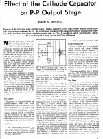
Bypass PP Cathode Resister Or Not?
This is a good read, something you have already discussed with others. Unbypassed is OK for Class A. But your amp has conflicting requirements.
On the one hand you need to decrease the B+ requirements to reduce PT heating. But if you do that the PP pair will be driven farther into Class AB territory.
Another seldom discussed subject is the dependence of Gm on cathode current. Reduced cathode current lowers Gm. That means rp, the plate resistance goes higher, something you don't want driving your 4K P-P OPT.
There is much advice given here on DIY & elsewhere, a lot of it is based on opinion without any supporting data. Opinion is just that, opinion. Might be OK, ask where the opinion came from. Otherwise may be simply 'Fake News'.
Attachments
Last edited:
I appreciate the advice John. As a newbie to all of this, it is very challenging to tell the difference between opinion and fact. That's what I get for jumping in with both feet without being educated - however that's sort of how I learn best.
I have another unrelated question about this amp. When I switched from U/L to triode mode (years ago), I left the feedback in place based on a recommendation at the time. For the heck of it, I disconnected feedback the other day and tested the amp. The result was quite surprising. I was monitoring cathode voltage with my DMM at the time. I noticed that the voltage was fluctuating based on the volume knob position. Then I tried cranking it to maximum volume. Cathode voltage plummeted (I am convinced it would have hit zero if I had left it) and I heard the "tinkling" sound of the tubes similar to when they are warming up or cooling down. A soon as this happened, I turned the volume knob back and the system became stable again. I repeated the action a couple more times and the result was the same.
I re-connected feedback after that but I have been curious about what was going on ever since.
Learn by doing, the 'hands on experience' is a great way to go. That is exactly how many of we fossils gained the knowledge we have, often in several fields.
When you reconnected your amplifier to go from UL to triode mode the NFB probably changed from something like 20 db to about 14 db, the triode output stage had less gain than in UL mode. Less gain inside the loop, less NFB unless the FB path is changed. Stability would be better too. With the NFB unhooked the amp gain would increase quite a bit. Driving the speakers full out like that can often causes failures.
But with the output section connected as triodes, any really violent voltage swings are heavily damped by whichever of the triodes in the PP stage are conducting. What you have is a built in "SYA', a Save Your *** bypass circuit. But If you did that on a PP pentode amp the voltages generated could be sufficient to cause insulation failure in the OPT. Without actually seeing what you did it looks to me there was 'grid blocking'. The grids on the output tubes conduct & a negative charge accumulates on their grids, biasing them to lower or no conduction.
In the hands of an experienced tech, engineer or others much information about the health of a circuit can be gained. Your amplifier is a direct descendant of the Mullard 5-20. Thousands have been built both by amateurs & professionals. The schematic is easy to follow & when properly put together is almost bullet proof. A great starter circuit. And a very good performer.
The front end In your version, usually a low noise pentode EF86 has been converted to a cascode stage. The cascode circuit has the low noise of a triode & the gain of a pentode. But as the front end of an audio power amplifier, the extra complexity is not warranted. If there is noise at the front end it will be caused by some other factor, failure of a part, Etc. But never fails to impress the cheering cascode fans. Cascode front ends are useful in high frequency RF front ends such as in FM receivers.
The rest of the audio section of the amplifier is very ordinary.
The power supply is a problem, the manufacturer has decided to go cheap. First the PT seems under rated. Designers usually specify a PT with something like 2X the load. In this case that would include the AC heaters & the DC B+. Designing for capacitor input filter system is not difficult, as long as provision is made for the large RMS current that causes quite a bit of heat. Unfortunately an inexperienced designer can easily overlook that problem. And they often do.
This designer tries to avoid a filter choke by inserting an exceptionally large cap as the first after the rectifier. Large RMS currents are a sure thing. If the rectifier were a vacuum tube it could fail during the first turn on. But lifetime would be compromised in any case.
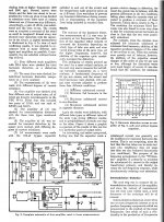
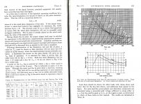
The pages from JD Ryder's text book on Electrical Engineering that cover the triode curves for power output & D% is attached. These curves apply to any triode, they are generic. Only the scale factors are different. During the time before the Earth cooled we calculated these things with pencil & paper, calcs done on a slide rule. Today a spread sheet would help a lot. Once set up could be used for many tubes, just stuff in the plate curves.
When you reconnected your amplifier to go from UL to triode mode the NFB probably changed from something like 20 db to about 14 db, the triode output stage had less gain than in UL mode. Less gain inside the loop, less NFB unless the FB path is changed. Stability would be better too. With the NFB unhooked the amp gain would increase quite a bit. Driving the speakers full out like that can often causes failures.
But with the output section connected as triodes, any really violent voltage swings are heavily damped by whichever of the triodes in the PP stage are conducting. What you have is a built in "SYA', a Save Your *** bypass circuit. But If you did that on a PP pentode amp the voltages generated could be sufficient to cause insulation failure in the OPT. Without actually seeing what you did it looks to me there was 'grid blocking'. The grids on the output tubes conduct & a negative charge accumulates on their grids, biasing them to lower or no conduction.
In the hands of an experienced tech, engineer or others much information about the health of a circuit can be gained. Your amplifier is a direct descendant of the Mullard 5-20. Thousands have been built both by amateurs & professionals. The schematic is easy to follow & when properly put together is almost bullet proof. A great starter circuit. And a very good performer.
The front end In your version, usually a low noise pentode EF86 has been converted to a cascode stage. The cascode circuit has the low noise of a triode & the gain of a pentode. But as the front end of an audio power amplifier, the extra complexity is not warranted. If there is noise at the front end it will be caused by some other factor, failure of a part, Etc. But never fails to impress the cheering cascode fans. Cascode front ends are useful in high frequency RF front ends such as in FM receivers.
The rest of the audio section of the amplifier is very ordinary.
The power supply is a problem, the manufacturer has decided to go cheap. First the PT seems under rated. Designers usually specify a PT with something like 2X the load. In this case that would include the AC heaters & the DC B+. Designing for capacitor input filter system is not difficult, as long as provision is made for the large RMS current that causes quite a bit of heat. Unfortunately an inexperienced designer can easily overlook that problem. And they often do.
This designer tries to avoid a filter choke by inserting an exceptionally large cap as the first after the rectifier. Large RMS currents are a sure thing. If the rectifier were a vacuum tube it could fail during the first turn on. But lifetime would be compromised in any case.
The pages from JD Ryder's text book on Electrical Engineering that cover the triode curves for power output & D% is attached. These curves apply to any triode, they are generic. Only the scale factors are different. During the time before the Earth cooled we calculated these things with pencil & paper, calcs done on a slide rule. Today a spread sheet would help a lot. Once set up could be used for many tubes, just stuff in the plate curves.
Attachments
Thanks John!
It sounds to me like the very first thing I should do is take your original advice about replacing the giant cap after the rectifier with a smaller value (~200uF). Perhaps I will do that and then do some measuring. Maybe I don't need to mess with the cathode bias resistors at all.
It sounds to me like the very first thing I should do is take your original advice about replacing the giant cap after the rectifier with a smaller value (~200uF). Perhaps I will do that and then do some measuring. Maybe I don't need to mess with the cathode bias resistors at all.
If not going for a typical CRC filter then another option is to keep the 470uF cap and just put a resistor before it.
But the real answer is a CRC filter with values that give you the correct voltage and minimizes the charging spikes. Even better is CLC but as you mentioned earlier there is no room for a choke.
PSUDII will give you all the answers.
But the real answer is a CRC filter with values that give you the correct voltage and minimizes the charging spikes. Even better is CLC but as you mentioned earlier there is no room for a choke.
PSUDII will give you all the answers.
I've just discovered another local electronics components store (the one I used to go to shut down) so now at least I won't have to buy online at the usual suspects, pay through the nose for shipping, and wait ages for the stuff to arrive.
I am going to check the place out soon and if they have stock (at reasonable prices) I will buy enough stuff for a CRC and also the dedicated cathode bias resistors and bypass caps (as it is in a typical Mullard 5-20).
I am going to check the place out soon and if they have stock (at reasonable prices) I will buy enough stuff for a CRC and also the dedicated cathode bias resistors and bypass caps (as it is in a typical Mullard 5-20).
- Status
- This old topic is closed. If you want to reopen this topic, contact a moderator using the "Report Post" button.
- Home
- Amplifiers
- Tubes / Valves
- P-P EL34 Modification