I know this has been covered before, but not in great detail in terms of Zpri. For bog standard PP with two valves we 1/2 the OPT Zpri for class A,1/4 it for class B. So for two valves in parallel does that mean we divide that by 2, EG 1/4 for Class A & 1/8 for Class B?
I feel i should have this straight in my head but for some simple calculations my brain starts going into meltdown,going around in circles.
Andy.
I feel i should have this straight in my head but for some simple calculations my brain starts going into meltdown,going around in circles.
Andy.
Ok,but not by much though, roughly 100 ohms ish.My sim agreed with you, but should take DCR into calculation as it increases output Z, exp for high power output.
Thanks for clarifying.... in which case though that means that anode current is double yes?When paralleling tubes, each one/each pair sees a load that's double/three times etc
Andy.
Subbing in a backup tube
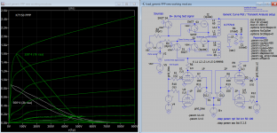
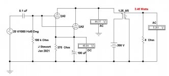
What happens if we need to stuff in an alternative to cover for a failure? A 45 does reasonably well in a 2A3 socket. On a temporary basis only.")
Not the answer on loadlines asked for but an interesting sideline.
What happens if we need to stuff in an alternative to cover for a failure? A 45 does reasonably well in a 2A3 socket. On a temporary basis only.
Not the answer on loadlines asked for but an interesting sideline.
Attachments
Thanks.That's right, given you keep biasing the tubes the same.
Not sure where your coming from there me old duck, I make all my amps with adjustable bias, adjustable CCS's and what have you = more leeway to make changes.What happens if we need to stuff in an alternative to cover for a failure?
Andy.
Yes, the 2A3 does almost all of the work.
The 45 is only there to fill the socket.
2A3 rp = 800 Ohms, u = 4.2 (Lowest impedance and highest gain). The Ox
45 rp = 1700 Ohms, u = 3.5 The young Calf.
2A3 tubes are currently produced, and are not expensive.
45 tubes are only available as new old stock and they are very expensive, or used and of questionable performance;
Or they are extremely expensive current production, but are not a real 45.
It is better to keep some 2A3 tubes on hand, instead of using a 45 to fill a 2A3 socket.
Do you want to use a 45?
Then build a 45 amplifier, do not waste a 45 in a 2A3 amp.
Last edited:
True,
It is an exercise.
And, doing the illustration in Parallel Single Ended is simpler.
The original post question was for Push Pull Parallel operation.
Threads often diverge from the original post.
That is a positive feature, and a negative feature.
But much is learned in the process.
I give most threads a Positive grade.
When paralleling tubes, each one/each pair sees a load that's double/three times etc. the OT's nominal primary impedance.
Yep. Using N tubes in parellel is like using a single tube that passes N times the current. Just use the curves of a single tube and multiply the current labels on the y-axis by N.
And divide the load impedance by N times.
And divide the DCR of the primary by N times.
And multiply the laminations by N times.
And divide Rg by N times.
And divide the driver impedance by N times.
And multiply the driver current by N times.
And multiply the B+ current by N times.
And divide the ripple by N times.
And multiply the filament current by N times.
And multiply the bias circuitry by N times.
Did I forget anything?
Simple, Huh?
Last edited:
It is an exercise.
And, doing the illustration in Parallel Single Ended is simpler.
The original post question was for Push Pull Parallel operation.
So shew us how you would do that. With some images & proofs. And some supporting equations to indicate what that is. Sofar I've seen much BBB passed on as advice by you. A fog of BS.
And finally, give us a photo & schematic of something, anything that you've built in the last 20 yrs to shew the advice you pass out is based on hands on experience. Not the experience you got at TEK pushing paper. A working example, with tubes in it. Not the carefully crafted wooden box that passes for a chassis.
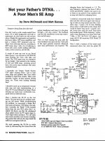
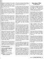
How to Destroy an Otherwise Good Dyna Amp
Dave is a little shy about his experience with the building of audio amplifiers.
By his own admission, most were from kits. From Sound Practices Magazine attached is one of the only examples I know of that goes beyond a kit for all to review. Much of what Dave comments on here on DIY is OK. But I don’t think I’ll be asking for his help any time soon!
Sound Practices was quite a good publication. It was put away like many others
by the iNet. I corresponded with Dave Roberts a couple of times, he confided that many of the projects he got, the contributors at times had problems getting
their projects to work properly. NTL, I subscribed to Sound Practices & have
a complete set. Its still a very good resource.
There were some excellent contributors to SP, such as Alan Douglas.
Some here may recall Alan had authored books on tube testers. He was an
expert in regard to the genealogy of tubes, many wish he had put down his thoughts on that subject as well.
Attachments
Don’t let desk-butt get you down gents.
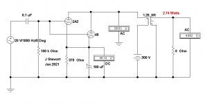
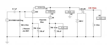
So, according to Kirchhoff the 2A3 is swinging 58,04 - 43,09 = 14,95V? Or should the secondary voltage be included? [forgetting that energy is lost and power dissipated when a capacitor is repeatedly charged and discharged in an AC circuit, power dissipation is reported to be C*V*V*f]. What lessons could be derived?
Double impedance gives 1/4 the current involved;
Half impedance gives 1/4 output voltage.
There is a relation
Attachments

Last edited:
- Status
- This old topic is closed. If you want to reopen this topic, contact a moderator using the "Report Post" button.
- Home
- Amplifiers
- Tubes / Valves
- Drawing load lines for parallel PP OP stages.