Well, that explains a few things. I didn't know that impedances were dynamic, respective of the actual loads in place. I forgot that the OPT I'm using has a center-tapped secondary. I've been using that, so it should actually be 300 ohm, but that's still too high. That being said, would that not dramatically reduce the output power versus using a transformer with the correct impedance? The 6H30s are an actual option. It would just be a very expensive mistake to make if I couldn't use them/don't need them. 6V6's would also be an option, but I would think I'd need something more along the lines of 250v B+ to keep them in linear country, would I not? Or could they be tamped down and still be running at 350v? The 6V6GT in that radio was pushed to 7.5 watts in SE according to the schematic. New OPT's would also be an option. I just want it done correctly and safely.
Last edited:

I figured it would still be wildly out of spec for what was needed. I was just correcting myself. I've got those 12k PP OPTs in my cart. Since they'll take a few months to arrive anyway, I'd like to get a more appropriate power transformer while ordering so I don't have to use a doubler. I'd like to aim closer to 250v for the sake of the 6FQ7's. It looks like the 12AT7 would need a tiny plate resistor to be able to draw enough current though. Maybe I'm just misreading the datasheet. Not sure.. Would another tube be more appropriate? I'm ordering stuff anyway. Might as well look at that too.
350-400V plate voltage is good to have if you use proper primary load for the 6FQ7 which is in the 25-30 Kohm range for normal push-pull (half for parallel). You can always drop some voltage adding a regulator which is another good thing to have.
The voltage doubler is not a bad idea because if you want to try the ECC99 or 6H30 at lower plate voltage you can do it later without changing the power transformer. The Edcor would be 24K with 32R headphones. Right now the output transformer is the bottle-neck.
With lower plate resistance tubes like the ECC99 and 6H30 you still need 5K minimum, better if 10K or more....
The higher primary load will also limit output power with less distortion if properly biased.
As a guideline for the 6FQ7 you can use the ECC40 datasheet. Here you can see how this tube is used both in SE and PP in output stage. The secondary load is not relevant, in the sense that can be whatever it needs to be.
Last edited:
It all depends on what one needs to drive. Some headphones are beefy too and small tubes like the ECC99 are not comfortable in OTL output stage. Possibly the Russian triode 6C19pi (6S19P) is a better all-around choice. From 2 of these per channel in classic OTL circuit it's rather easy to get 1W into 32R load, more power going up to 600R load.
Can find a quad of 6S19P for 16$ shipping included from Russia....
Can find a quad of 6S19P for 16$ shipping included from Russia....
Well, I got the OPT's ordered. I also ordered a pair of ECC99s so I'll have something else to mess with. As for that ECC99, would I need to use something like a 6DJ8 cascoded on the front end? I happen to have a pair of those. I've heard that they can be difficult to use with a potentiometer for volume.
Why is it hard to use a volume control with cascode 6DJ8???
You heard?
The cascode has low gain on the lower tube, because it is loaded by the top tube's cathode.
The 6DJ8 is an RF tube, with low grid to plate capacitance.
So those 2 factors make the Miller Effect Capacitance quite low.
That makes the high frequency loading of the volume control an easy load.
One real difficulty of using a 6DJ8 in cascode, is the top cathode is typically at a higher voltage than the cathode to filament maximum voltage specification.
That requires a 2 resistor voltage divider, from the B+, and a bypass cap across the lower resistor, to elevate the 6DJ8 filaments.
The original 6DJ8 specifications had a higher specified cathode to filament voltage for one of the triodes, and a lower specified cathode to filament voltage for the other triode.
The other problem with using cascode operation, is the 6DJ8 in that mode used a high impedance load for the top triode's plate (a high Q resonant circuit).
That is because the top plate of a cascode is high impedance.
Using a lower load impedance the gain goes down.
But using a higher load impedance the output impedance is high, and can not drive a following stage that has low to medium input impedance.
The next stage grid resistor, rg, and the next stage Miller Effect Capacitance are the load impedance that the cascode's top plate sees.
Last edited:
Let us use a single triode of the 6DJ8 as a gain stage. Common cathode connection.
Consider using a 50k volume control to the grid.
Drive the 50k pot with a CD player that has 1k Output impedance (rated to drive 10k, but that has 1k output impedance).
Use a high resistance plate load, or a current source for the plate load (but only to get gain almost as high as u, so that the high frequency rolloff will be at its worst case.
At -6dB on the volume control setting, the 6DJ8 is driven by about 25k impedance (the worst case volume control setting in the above example, versus high frequency roll off).
6DJ8
u =33
grid to plate capacitance is 1.4pF
grid to cathode, heater, and internal shield 3.3pF
If you can even get gain = u (33), we have (1.4pF x 33) + 1.4pF = 47.6pF of Miller Effect Capacitance + 1.4 pF grid to plate capacitance.
47.6pF + 3.3pF = 50.9pF, call that 50pF.
Xc of 50pF = 25k @ 127kHz.
The high frequency -3dB point is 127kHz.
The high frequency -1 dB point is 63kHz.
Change the volume control to a 100k potentiometer.
-3 dB at 63kHz.
-1 dB at 31kHz.
That looks pretty good to me.
What seems to be a problem with using a volume control in front of a 6DJ8?
Do not believe everything you read; especially if I wrote it.
Last edited:
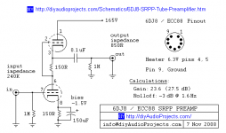
Lol, dunno. I don't remember where I saw that at. The fact that it was wrong though makes things easier. I had a little trouble getting the 6dj8's to draw enough current back when I was playing with them. 6mA was about as good as I could get, and that was with a tiny plate resistor. When I tried them with the doubler, they wouldn't draw enough current for the plate resistor to drop the voltage. I got frustrated and put them aside. I'm going to have to give them another shot now.
I found this schematic. B+ is spot on for what I've got to work with. Anything scary about it that you can see?
I found this schematic. B+ is spot on for what I've got to work with. Anything scary about it that you can see?
Attachments
Last edited:
Did you use a single triode, and a plate load resistor?
Or did you use the schematic in Post # 37?
6mA in that preamp would only have 0.9V bias.
What is the signal source that drives the volume control, and from the volume control to the 6DJ8 grid?
What is the voltage output of the signal source?
A typical CD player has 2.0 Vrms out (2.8V peak at full scale signal).
Your preamp schematic with only 6mA, and 150 Ohm bias resistor only has 0.9V bias.
0.9V / 6 mA = 150 Ohms
The 2.8V peak from a CD player is over 3 times larger than the 0.9V bias.
If you only have 0.9V bias, the preamp needs to be used to amplify a smaller signal, like a phono cartridge.
Perhaps your preamp was oscillating at VHF, and only drawing 6mA average (Very High Frequency RF). No grid stoppers, and the wiring placement might have caused that.
But with 165V B+, there was only about 82V across each triode, less than the typical 90V in the data sheet standard operation.
Was the 6DJ8 tested for emission?
The schematic in Post # 37 is an SRPP stage. It is not a cascode stage.
What is the schematic of the 6DJ8 circuit where you only got 6mA with 165V B+?
Last edited:
I haven't tried the schematic in post 37. I just found it while looking for 6DJ8 amplifier schematics. I was using a single triode with a plate load resistor of (i think) about 10k, and I was feeding it audio from my bench PC. I'm not sure of the signal strength. I'll be able to take measurements this weekend. Another thing I've heard about the 6DJ8 is that it likes to oscillate. I've seen it said that the grid stopper needs to be right on the tube socket. I planned to do that in final implementation, but it's problematic with the breadboard/prototyping setup I have at the moment. It's possible that it was indeed oscillating at a very high frequency. To my knowledge, neither of the two 6DJ8s that I have were tested for emission. I bought them from a reputable seller on Ebay, but it's Ebay so that could mean anything at the end of the day.
When you do the measurements this time, check the bias voltage, the plate to cathode voltage, and the plate current (if the grid is not drawing current, the cathode current is the same as the plate current; and with self bias, is easy to check: current = cathode Volts / Rk Ohms).
Then, find the plate voltage and the plate current on the tube graph, and see if the grid voltage lines show that the bias voltage you have intersects with the plate current and plate voltage that you got.
It should be close, unless the tube is bad, or the tube is oscillating.
The 6DJ8 is a high transconductance tube.
At medium plate current, the 6DJ8 will change its plate current by 12.5mA/Volt of bias change.
A little change of bias voltage makes a large change in plate current.
80mV bias change = 1mA plate current change.
With a resistor in the plate circuit, the change will be less, because the plate voltage will also vary as the change in plate current causes a change in the drop across the plate load resistor.
With a 10k plate resistor, a 1 ma change in plate current will change the voltage drop across the 10k to change by 10Volts.
At medium current, the 6DJ8 plate resistance is about 2.5k (in round numbers).
A 10Volt change in the plate resistor voltage drop, will change the plate current by the amount of
2.5k x 1mA = 2.5Volts.
So if the plate load tries to change by 10Volts because of a 1 mA change in plate current, but the plate tries to change by 2.5V because of a 10V change from the 10k . . .
that interacts to give the actual voltage that it settles to.
But, it should land somewhere near the plate curves, at the intersection of plate voltage, plate current, and grid bias.
Otherwise, we are back to either an oscillation, or a bad tube.
Last edited:
- Status
- This old topic is closed. If you want to reopen this topic, contact a moderator using the "Report Post" button.
- Home
- Amplifiers
- Tubes / Valves
- PP Triode Choice & Output Impedance