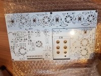
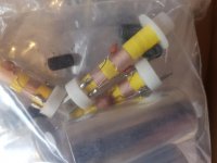
OK so I thought I'd build something different from an amp. I had given up with getting the coils for the IF, but then came across this kit.
Vintage Valve Tube FM Radio DIY Kit Stereo Receiver Frequency Modulation Board | eBay
Its from China and probably a copy of something. However its comes with newly wound double tuned IF coils and a double sided PCB of very good quality with ground floods on both sides. The tuning cap is a reused unit but I would like to change the design to synthesised varicap tuning.
There's a schematic here:
IWISTAO Tube FM Stereo Radio Tuner Finished PCBA Preamplifier Version No Including Power Transformer HIFI Audio 110V/220V DIY|hifi wire|transformer currenthifi component - AliExpress
I don't have consent to put in the one I have.
I have test equipment to get the thing up and running.


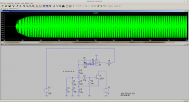
The plan is to put in a synth SA1057 on a copper clad board in place of the big tuning cap. I wanted to reuse the 6C11/EC81 oscillator which is in a Hartley configuration. However on simulation to voltage across the tank circuit is so big I cannot use varicap tuning. Anybody got any ideas here?
If not I plan to place a J309 JFET oscillator on the same board as the synth and covert the 2C11 into a LO buffer. Something like this:

I also will add a third tuning stage at the antenna input to improve image rejection.
If not I plan to place a J309 JFET oscillator on the same board as the synth and covert the 2C11 into a LO buffer. Something like this:

I also will add a third tuning stage at the antenna input to improve image rejection.
I would like synthesised tuning and a display and presets. The unit has no AFC.
So if anybody can suggest if the 2c11 osc can be modified for varicap great - if not I will try a JFET approach.
I have wound coils yes but even getting the formers is tricky. Also getting the correct coupling factor takes time. The IF bandwidth needs to be around 250KHz for stereo. This approach should give me a working IF strip so I can concentrate on the front end performance.
Last edited:
Have you looked at Das UKW-Projekt?
And especially the IF stage (ZF-Stufe).
Most of the IF coils are still available at Audioröhrentechnik Ausgangstrafo Übertrager Bandfilter Spulen Röhren Audio Fassungen 516201 516228 516236 516260 516686 NF-Übertrager Drossel Trafo Hifi Highend.
And especially the IF stage (ZF-Stufe).
Most of the IF coils are still available at Audioröhrentechnik Ausgangstrafo Übertrager Bandfilter Spulen Röhren Audio Fassungen 516201 516228 516236 516260 516686 NF-Übertrager Drossel Trafo Hifi Highend.
Kay the only thing I could think of was post #2. All the valve oscillators I have seen seem to generate over 100v or more across the tank circuit. The 2c11 generates 200ppk on simulation. I was thinking of a JFET osc and synth on the same copper clad board and converting the 6C11 into a LO buffer to get the bigger signal needed by the mixer and keep a similar topology.
Last edited:
Kay the only thing I could think of was post #2. All the valve oscillators I have seen seem to generate over 100v or more across the tank circuit. The 2c11 generates 200ppk on simulation. I was thinking of a JFET osc and synth on the same copper clad board and converting the 6C11 into a LO buffer to get the bigger signal needed by the mixer and keep a similar topology.
100V oscillator voltage ?! Jeeez, I think I can receive that signal over here when you switch the oscillator on.
Limiting the oscillating voltage of oscillators is a matter of adding non-linearity across the oscillating LC circuits. Two diodes should provide a peak oscillatory voltage of about 0.3V. If a thermionic diode is used this voltage is higher as these use more voltage compared to semiconductors.
I have done this limitation technique under LTSpice and it works.
I have done this limitation technique under LTSpice and it works.
Last edited:
That sure looks like a 2 section AM plus 2 section FM air variable tuning capacitor. IMO, no TRF front end stage exposes you to "image" interference. As you are already contemplating a SS local oscillator as part of varicap tuning, add a FET TRF stage in front of the 1st detector.
Tube IF transformers for both AM and FM can be sourced from Germany. Look here. Danke Deutschland!
Fair Radio still shows suitable NOS 3 section air variable tuning caps., at a nice price.
Tube IF transformers for both AM and FM can be sourced from Germany. Look here. Danke Deutschland!
Fair Radio still shows suitable NOS 3 section air variable tuning caps., at a nice price.
It is I have it here. Its the only non-new part but they explain this. Yes would like to convert to 2 stage RF tuning. Would also like to improve sensitivity. Will look at this next. May use JFET + 3N3 cascade or just JFET amp which may be easier to implement. Although quite a few mods will learn a lot! Not sure whether to place the tank before the JFET or after. If I go cascade (jfet drain to cathode of 6n3) would have to go before. If i am really clever can arrange a tracking notch for the image. Looking at the component valves I think the LO side will be low. I prefer the JFET LO as having not done this before I would be worried about the heater AC modulating the LO.
Last edited:
The still available 3SK263 dual gate MOSFET just might make a very nifty TRF front end.
Warnings abound about oscillation, when "tank" circuits are present in both the gate and drain circuitry of FETs. Refer to the "ancient" tuned grid/tuned plate oscillator. This fact was a driving force for the introduction of ceramic filters in FET based IF strips.
Warnings abound about oscillation, when "tank" circuits are present in both the gate and drain circuitry of FETs. Refer to the "ancient" tuned grid/tuned plate oscillator. This fact was a driving force for the introduction of ceramic filters in FET based IF strips.
- Status
- This old topic is closed. If you want to reopen this topic, contact a moderator using the "Report Post" button.
- Home
- Amplifiers
- Tubes / Valves
- Valve FM receiver