I came across this old article the other day and also discovered that I have a lot of the components in my spares bin.
I've got a pair of Hammond 1650H output transformers. I'm not sure if they are a perfect match for this circuit ?
YES. I'm aware that there is a mix-up in the capacitor values and voltages but I can play with those.
Has anyone built this from 1992 ?
I've got a pair of Hammond 1650H output transformers. I'm not sure if they are a perfect match for this circuit ?
YES. I'm aware that there is a mix-up in the capacitor values and voltages but I can play with those.
Has anyone built this from 1992 ?
Attachments
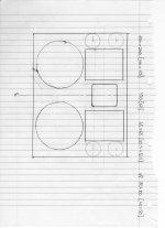
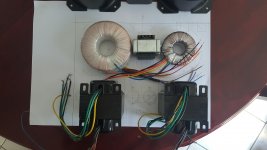
This is my physical plan - any comments would be welcome.
T2 and T3 are different sized toroids but are disguised under identical shielding cans.
T4 is an EI transformer also disguised under a cover between the two output transformers.
The 4 x EL34s are on the outside edge.
The chassis size is limited to match the other components in my system.
T2 and T3 are different sized toroids but are disguised under identical shielding cans.
T4 is an EI transformer also disguised under a cover between the two output transformers.
The 4 x EL34s are on the outside edge.
The chassis size is limited to match the other components in my system.
Attachments
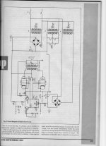
For ease of viewing, let's rotate the schematic.
An obvious improvement is regulating EL34 g2 B+. Bring the open loop IMD down!
The linearity of SS voltage amplifiers is always subject to question. I don't pretend I understand the ramifications of how that setup implements loop NFB.
An obvious improvement is regulating EL34 g2 B+. Bring the open loop IMD down!
The linearity of SS voltage amplifiers is always subject to question. I don't pretend I understand the ramifications of how that setup implements loop NFB.
Attachments
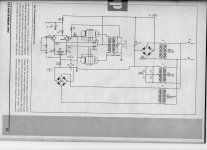
I might need to experiment with the value of R in the CRC for B+
With the errors in the article with C and V values I'm currently opting for 220uF 400V / 1K0 / 220uF 400V in place of C3.
I might go for CRCRC with 3 x 220uF 400V and 2 x 470R.
I've got enough 220uF 400V to use 5 of them in CRCRCRCRC with maybe 220R as R.
With the errors in the article with C and V values I'm currently opting for 220uF 400V / 1K0 / 220uF 400V in place of C3.
I might go for CRCRC with 3 x 220uF 400V and 2 x 470R.
I've got enough 220uF 400V to use 5 of them in CRCRCRCRC with maybe 220R as R.
Why the high value resistance? I think 1k there will drop ~60V.I'm currently opting for 220uF 400V / 1K0 / 220uF 400V in place of C3...
Transformer orientation
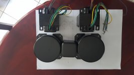
At last some of the hardware is starting to arrive.
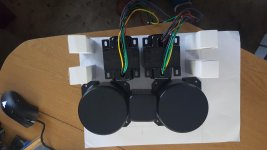
This is my current plan.
The three mains transformers are at the back, their different profiles being carefully disguised in metal cans.
The two toroids are the HT and Heater supplies, there is a smaller EI transformer between them providing the 60V grid supply under the square can. This is to be mounted so that the mounting screws are hidden under the toroid covers.
Which way would be best for the output transformers ?
The 4 x EL34s are destined to be mounted in a line as shown in pencil.
The main reservoir caps are internal to the chassis as modern components are far smaller than their antique cousins.
At last some of the hardware is starting to arrive.
This is my current plan.
The three mains transformers are at the back, their different profiles being carefully disguised in metal cans.
The two toroids are the HT and Heater supplies, there is a smaller EI transformer between them providing the 60V grid supply under the square can. This is to be mounted so that the mounting screws are hidden under the toroid covers.
Which way would be best for the output transformers ?
The 4 x EL34s are destined to be mounted in a line as shown in pencil.
The main reservoir caps are internal to the chassis as modern components are far smaller than their antique cousins.
Attachments
Last edited:
Ultra Linear mode will give a little less output power than Pentode mode.
Ultra Linear mode will also mean that the global negative feedback will not have to correct
quite as much distortion, as in Pentode mode.
Suppose the amp is stable in Pentode mode, with the output transformers you have, and into the varying impedance and reactance of your loudspeakers.
Then, if you re-wire the amp for Ultra Linear mode, it should be even more stable into your loudspeaker loads, and into other loudspeaker loads (without any adjustment of the negative feedback network).
Try it. The path to Ultra Linear mode is a simple 10 minute wiring job, including the time to get the soldering iron warm.
Caution! If you do not have any Bleeder Resistors, be ready for a shocking experience!
Check the B+ voltage before getting your hands and elbows into the amplifier.
Safety First! Prevent the "Surviving Spouse Syndrome".
Your schematics do not show any bleeder resistors!
Get them in there first. You will need to very carefully clip them in with clip leads, to get the B+ caps fully discharged. Then wire the bleeder resistors in, before you do any more wiring changes (like converting to Ultra Linear).
Your Mileage May Vary.
Last edited:
At last some of the hardware is starting to arrive.
This is my current plan.
The three mains transformers are at the back, their different profiles being carefully disguised in metal cans.
The two toroids are the HT and Heater supplies, there is a smaller EI transformer between them providing the 60V grid supply under the square can. This is to be mounted so that the mounting screws are hidden under the toroid covers.
Which way would be best for the output transformers ?
The 4 x EL34s are destined to be mounted in a line as shown in pencil.
The main reservoir caps are internal to the chassis as modern components are far smaller than their antique cousins.
I don't think the transformers are ok they look so close to the tubes I recommend at least 2 inches within other tubes or transformers a power tube will toast a transformer if they are so close, I think a diferential tube input stage and mosfet as drivers will be far linear than a pair of transistor as LTP alone check the EL34 baby huey post that design will rock, it only uses a 12ax7 per channel if you dont want to use many tubes
Last edited:
I was hoping for some comments regarding the HAMMOND 1650H output transformers in this application.
Personally, no, I wouldn't use a 6.6k OPT with EL34. But you need to ask the designer of that circuit. Or draw the load lines and figure out where you want those tubes to operate.
6.6k may give a little less power, than say 4.3k.
But how much power do you need?
The open loop gain is lower at the output with 6.6k versus 4.3k; but the gain to the output tube plates is higher with 6.6k.
The negative feedback ratio will change slightly.
Take an 8 Ohm speaker that has 6 Ohms minimum impedance (6 Ohms is typical for an 8 Ohm rated speaker), and you connect it to the 8 Ohm tap, that changes 6.6k to 4.95k.
I think you can worry about all this, but I expect it to work quite good.
If those transistors do not break down, and as long as you can make the negative feedback stable with a loudspeaker load, the amp should work well.
In Photography, there is a quote: The worst picture is the one you did not take.
In Hi Fi Stereo: "The worst sounding amplifier is the one you did not build".
I am only guessing, but I think you are not building an amplifier to run circles around the most expensive and highest performance EL34 amplifier that is currently produced by a large manufacturer (you are not going to quit your job, and go into the amplifier business).
I bet you are building something to be proud of, and to enjoy listening to.
Last edited:
Your schematics do not show any bleeder resistors!
Get them in there first. You will need to very carefully clip them in with clip leads, to get the B+ caps fully discharged. Then wire the bleeder resistors in, before you do any more wiring changes (like converting to Ultra Linear).
Your Mileage May Vary.
There are indeed bleeder resistors across B+ they are not shown in the schematic.
- Status
- This old topic is closed. If you want to reopen this topic, contact a moderator using the "Report Post" button.
- Home
- Amplifiers
- Tubes / Valves
- ETI Hybrid EL34 amplifier