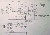
Hello Guys..me seek advice and guidance for the attached schematic below. Am not sure I did it right for the EL34 grid with a plate choke in series!? A 140H redundant from my EL33 built. I'm no EE and have no scope to check it's performance except depending on my 77 yrs. old ears for judgement. Initially, it was triode strapped but now it's pentode mode. Honestly, not as smooth but like they said, everything is a compromise. Wow..it wake-up my 604E, more meat on the bone and oooomph!
Thanks for dropping by!
Don't take chances, stay Healthy!
Thanks for dropping by!
Don't take chances, stay Healthy!
Attachments
Alright, interresting! I'm slowly planning a GM70 build and was thinking of using an EL34 to be able to drive it into class A2 so this comes quite close in approach.
Can I ask why you are using "only" 480 volt on the anode of the 845? This is only the second time I see one of those big boy triodes with a B+ under 800 volt so I'm curious for your reasoning")
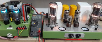
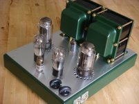
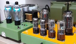
P.S. I wouldn't mind seeing a photos of your amplifier
Can I ask why you are using "only" 480 volt on the anode of the 845? This is only the second time I see one of those big boy triodes with a B+ under 800 volt so I'm curious for your reasoning
P.S. I wouldn't mind seeing a photos of your amplifier
I would omit this choke and connect the screen directly to the zener diodes string. A choke of this high inductance in this place counteracts to the screen grid's purpose.
Best regards!
Thanks, Kay!
An emitter or a source follower will out perform that zener string...improving PSRR...lower Zout etc.
Save your choke for another project or use it to load your first stage.
Care to share how it's being done...thkx!
@Zekk I meant more why you opted to go for about half a kilovolt of B+ for an 845 while most people choose about a kilovolt
This question should be direct to Dave Slager, who's a diehard low power 845 fan.
If it can function and partner well with my Altec 604E of 101dB, why crossover to a dangerous zone?
To be honest, it was built out of curiosity and with parts available in hand, let's tryout a low voltage, low cost, 845 SET! I was surprised it out-shine my EL 156 set, despite using expensive double-c OPT.
Attachments
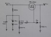
Second getting rid of the 35kOHm R and the zeners. Dropping 250-ish volts across 35kOhm is not going to allow much EL34 g2 current. MOSFET drain to 480, gate to resistive divider delivering the specified voltage and source to the EL34's g2.
Mind your heat sinking of the MOSFET. It will help some to put some resistance to ground so that the gm of the 'FET is higher at idle...but mind the dissipation/heat sink requirements.
I have a straight pentode amp under construction. Big sweeps, and their g2 V set based on the load at about 1/4 of B+. Heat sink resistance of 3 C/W and that is not as much margin as I would prefer.
If you can keep the EL34's g2 where you want it, I think you will quite like the result.
cheers,
Douglas
Second getting rid of the 35kOHm R and the zeners. Dropping 250-ish volts across 35kOhm is not going to allow much EL34 g2 current. MOSFET drain to 480, gate to resistive divider delivering the specified voltage and source to the EL34's g2.
Mind your heat sinking of the MOSFET. It will help some to put some resistance to ground so that the gm of the 'FET is higher at idle...but mind the dissipation/heat sink requirements.
I have a straight pentode amp under construction. Big sweeps, and their g2 V set based on the load at about 1/4 of B+. Heat sink resistance of 3 C/W and that is not as much margin as I would prefer.
If you can keep the EL34's g2 where you want it, I think you will quite like the result.
cheers,
Douglas
Thanks Douglas for the advice!
Can you post a schematic how it's done?
Best Regards.
Thanks Douglas for the advice!
Can you post a schematic how it's done?
Best Regards.
I can post a schematic of how I am doing it in the current build. Not quite sure that 'is how it is done'...
just how I am going to do it. I'll get it together shortly, most of this beast's schematic is just in my head.
cheers,
Douglas
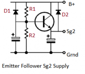
Sg2 supply
This may be useful.
Using a screen capture from John Broskie's tubecad,I post this picture.
The value of R1 and R2 can be arrived at by using this calculator.Voltage Divider Calculator.
This may be useful.
Using a screen capture from John Broskie's tubecad,I post this picture.
The value of R1 and R2 can be arrived at by using this calculator.Voltage Divider Calculator.
Attachments
I can post a schematic of how I am doing it in the current build. Not quite sure that 'is how it is done'...
I'll get it together shortly, most of this beast's schematic is just in my head.
cheers,
Douglas
How about the schematic post below?
Attachments
- Status
- This old topic is closed. If you want to reopen this topic, contact a moderator using the "Report Post" button.
- Home
- Amplifiers
- Tubes / Valves
- EL34 regulate g2 for 845 SET.