FlaCharlie: I listen to the amp daily, but I have put working on that amp aside for now as I have a couple of partially finished Pass amps (an Aleph J and an ACA) that I need to finish up. The amp took about four times as long as most amps do for me to complete. I did add a 33uF cap per side to the 30 nodes, but didn’t notice any change in sound. I am using La Scalas for testing, and they do have a -3 DB cutoff at around 55 Hz.
The only reason that this discussion came up was that several folks commented on the 2.2 uF value on the 30 nodes was “too low”, but not based on anything other than what is common usage. I asked for a definitive answer on how to figure out an appropriate value, and Bill Brown linked Loesch’s article. Other than that article, I still haven’t seen anything else from anyone else.
The only reason that this discussion came up was that several folks commented on the 2.2 uF value on the 30 nodes was “too low”, but not based on anything other than what is common usage. I asked for a definitive answer on how to figure out an appropriate value, and Bill Brown linked Loesch’s article. Other than that article, I still haven’t seen anything else from anyone else.
Last edited:
I don't understand this "problem". 
At "B+A" point al least 60dB PSRR (relative to B+) due to the PSU C-large R-C-large R-c filtrating.
The #30 anode current alteration is marginal versus output tube current, so "stressing" of PSU mainly due to the output.
The magnitude of "last C" of #30 anode circuit is almost negligible, the 1.5uF as good as 33uF.
If the B+ has 2Vpp hum, on the output only 36mVpp (shorted input), so the 35dB PSRR "thanks to" SE output.
Attachments
Fla Charlie, some thoughts:
You do a lot of underlining which implies to me a high level of confidence.
Loesch's article was largely a thought experiment, based both on a deep understanding of electronics and tons of experience experimenting and building. I am not a guy to "appeal to authority," but I would note that he is the primary designer for iFi and AMR. Somebody thought his ideas were worthwhile and backed him financially.
As a thought experiment it gives a lot to think about, though it doesn't mean that his cap sizes (or anything, really) are dogma.
He assumes a certain level of prior knowledge in the reader (you note he doesn't spell everything out).
Olson's article doesn't describe cap sizing as you note, but I think it is also informative in terms of understanding the role of the capacitor (and by extrapolation its size) when one understands its presence in series with the tube it feeds in an SE stage. This is the main takeaway, the implications re. sizing then left to the reader. The in-depth analysis of the ways to get this capacitor out of the current loop also implies that the cap is problematic, or at least worthy of attention (if it colors the sound it is in the signal path, right?).
I think tizman and I understand that the filter capacitors in a PS are in parallel (RC, low pass), but while in parallel to the PS, the final cap is in series with the tube it feeds (high pass). I suspect you may not believe this, but why? If it isn't, I would like to understand. Olson doesn't spell it out, but isn't the capacitor in series based on his circuit drawings?
I have been thinking a lot about the role of the plate load on the tube and don't have confidence about whether it has a role in any calculations.
As you note, Olson uses transformer coupling, many times without a loading resistor such that the tube is seeing essentially the "infinite" impedance of the next tube's grid. He also frequently provided regulated voltage to the driver tubes, this of course decreasing the impedance of the voltage to the stage (within the limits of VR tubes). As above, I am not sure what this means re. sizing, though his sizing of the cap is perhaps larger than typically seen and may be informative to tizman, or at least worth thinking about.
Re. tizman's question applying to the input stage, I am not sure why the articles wouldn't at least give food for thought. Aside from Rp's and RL's they are analogous, right?
All of the measurements of SE amps I have seen have a pretty significant (relative to SS) low-frequency rolloff. May or may not be significant re. listening, and certainly the output transformer has a lot to say based on its primary inductance, but it is still food for thought. Heck, maybe a little roll-off is desirable in terms of the transformer's saturation point in SE.
Re. the final capacitor's size, I agree, simulation could be helpful. The step response may be best/easiest(?). If, when the supply is stabilized, it is asked to change its current to a node, the change (drop) in voltage can tell you how "stiff" (regulated) the power supply is. Ideally, the PS should be able to supply enough current that it doesn't change, this one of the main benefits (in addition to noise) of a regulated supply (as Loesch notes and provides a circuit).
Your efforts at calculations re. the charging times of caps are interesting, this again relates to the supplies "stiffness" in the setting of different music types' demand on the PS and can inform sizing.
Finally, I am far from an expert, so nothing I say is dogma either. Far from it. There are many, many people here with more more knowledge and experience than me. I just tried to throw out some stuff as food for thought, nothing more. I almost never post despite reading this forum for 17 years (oh my, found that below my name- I must be getting old!).
Bill
Last edited:
euro21,I don't understand this "problem".
At "B+A" point al least 60dB PSRR (relative to B+) due to the PSU C-large R-C-large R-c filtrating.
The #30 anode current alteration is marginal versus output tube current, so "stressing" of PSU mainly due to the output.
The magnitude of "last C" of #30 anode circuit is almost negligible, the 1.5uF as good as 33uF.
If the B+ has 2Vpp hum, on the output only 36mVpp (shorted input), so the 35dB PSRR "thanks to" SE output.
Thanks for your comments.
I was one of those who had questions about the use of such a tiny cap to supply the input tubes and, as I said when I raised the question, it was mostly due to the fact that all the other designs I've seen, some from legendary designers, use a much larger cap.
Tizman speculated that the reason Decware used such a low value may have simply been to reduce cost. From what you're saying, it looks like that is likely the best explanation.
The introduction of Loesch's article, while interesting and perhaps valid in terms of sizing the B+ cap, just served to muddy the waters, though. Yes, it does discuss cap size, but it's all about the B+ cap that supplies the output tubes, whose requirements are vastly different than the input tube.
So you have confirmed my earlier suspicions that Loesch's calculations, which may be useful in sizing the B+ cap, are totally irrelevant when it comes to sizing the cap that supplies the input tube.
The Olson presentation is certainly informative but, as I pointed out, it has nothing to do with cap size at all. So it also is irrelevant in terms of determining the size of the cap that supplies the input tube.
Your conclusion seems to be that even the use of a tiny cap to supply the input tubes is sufficient. So it seems like perhaps there is no, single, optimal cap value for the input tube supply.
As for the claim that the PS forms a high pass filter, I followed the test procedure I suggested to Tizman earlier using my breadboard system.
While I'm waiting on some more DC Link caps to arrive, the cap I have clipped in to supply my input tubes is a 50uf motor run. I used a 50hz tone and listened with the 50uf cap and then with a 0.1uf 630v film cap. In a high pass filter such a drastic change would result in a much higher rolloff frequency and the 50hz tone would be greatly diminished, perhaps even inaudible.
While I have no equipment to measure with, except my ears, the 50hz output was the same level with both. So, no, it does not form a high pass filter.
I also compared the 50uf cap and the 0.1uf cap with music playing. Nothing with a lot of bass, just jazz. I couldn't hear any appreciable difference. I also monitored the voltage on the caps with the music playing and remained essentially the same and stable. It's possible that extremely bass heavy music may have an effect on voltage stability, I'll leave that for someone else to investigate.
FlaCharlie: Based on your experiment, it would appear that if Loesch’s method is relevant, then it is so for power tubes and not driver tubes. It would also appear that Decware’s 3.3 uF cap on the driver tubes is good design rather cost savings if more is not required. Also, as per capacitance adversely affecting sound quality, for example euro21 referring to too much capacitance making the tone “lazy”, isn’t better to not use too much capacitance when .1 uF will do?
Bill,Fla Charlie, some thoughts:
You do a lot of underlining which implies to me a high level of confidence.
Loesch's article was largely a thought experiment, based both on a deep understanding of electronics and tons of experience experimenting and building. I am not a guy to "appeal to authority," but I would note that he is the primary designer for iFi and AMR. Somebody thought his ideas were worthwhile and backed him financially.
As a thought experiment it gives a lot to think about, though it doesn't mean that his cap sizes (or anything, really) are dogma.
He assumes a certain level of prior knowledge in the reader (you note he doesn't spell everything out).
Olson's article doesn't describe cap sizing as you note, but I think it is also informative in terms of understanding the role of the capacitor (and by extrapolation its size) when one understands its presence in series with the tube it feeds in an SE stage. This is the main takeaway, the implications re. sizing then left to the reader. The in-depth analysis of the ways to get this capacitor out of the current loop also implies that the cap is problematic, or at least worthy of attention (if it colors the sound it is in the signal path, right?).
I think tizman and I understand that the filter capacitors in a PS are in parallel (RC, low pass), but while in parallel to the PS, the final cap is in series with the tube it feeds (high pass). I suspect you may not believe this, but why? If it isn't, I would like to understand. Olson doesn't spell it out, but isn't the capacitor in series based on his circuit drawings?
I have been thinking a lot about the role of the plate load on the tube and don't have confidence about whether it has a role in any calculations.
As you note, Olson uses transformer coupling, many times without a loading resistor such that the tube is seeing essentially the "infinite" impedance of the next tube's grid. He also frequently provided regulated voltage to the driver tubes, this of course decreasing the impedance of the voltage to the stage (within the limits of VR tubes). As above, I am not sure what this means re. sizing, though his sizing of the cap is perhaps larger than typically seen and may be informative to tizman, or at least worth thinking about.
Re. tizman's question applying to the input stage, I am not sure why the articles wouldn't at least give food for thought. Aside from Rp's and RL's they are analogous, right?
All of the measurements of SE amps I have seen have a pretty significant (relative to SS) low-frequency rolloff. May or may not be significant re. listening, and certainly the output transformer has a lot to say based on its primary inductance, but it is still food for thought. Heck, maybe a little roll-off is desirable in terms of the transformer's saturation point in SE.
Re. the final capacitor's size, I agree, simulation could be helpful. The step response may be best/easiest(?). If, when the supply is stabilized, it is asked to change its current to a node, the change (drop) in voltage can tell you how "stiff" (regulated) the power supply is. Ideally, the PS should be able to supply enough current that it doesn't change, this one of the main benefits (in addition to noise) of a regulated supply (as Loesch notes and provides a circuit).
Your efforts at calculations re. the charging times of caps are interesting, this again relates to the supplies "stiffness" in the setting of different music types' demand on the PS and can inform sizing.
Finally, I am far from an expert, so nothing I say is dogma either. Far from it. There are many, many people here with more more knowledge and experience than me. I just tried to throw out some stuff as food for thought, nothing more. I almost never post despite reading this forum for 17 years (oh my, found that below my name- I must be getting old!).
Bill
I'm not questioning the conclusions of either Loesch or Olson. I just don't see a direct connection between their writings and the question Tizman raised.
He wondered if there was a way to determine the optimal value of the PS cap that supplies the input tubes. Tizman's question had nothing to do with the B+ cap that supplies the output tubes, and nothing to do with current flow and how it varies when different topologies are employed.
And I absolutely agree that the B+ cap that supplies the output tubes in a SE amp is in the signal path. But that's not the cap that Tizman was concerned with.
In trying to figure out if Loesch's comments about the B+ cap also applied to the input tube's cap, he injected a calculator which I felt had only limited value. I feel that the cap recharge calculator that I posted is more useful and it doesn't inject questionable data about high pass and low pass filters. It only deals with cap recharging, which is unquestionably a key factor. It's simply a better tool for the job. Perhaps there are even better ones, though. And, as I said, it's of limited use because unless you know how much charge has been lost you can't determine the time needed to replenish it.
My understanding of theory is rudimentary at best and I generally avoid such discussions. Your grasp of it seems to be much more evolved than mine.
I'm pretty much a copy and paste builder, I'm certainly not a designer. I do enjoy using oddball tubes and trying slightly different configurations. This thread is of interest because I'm also working with what's been dubbed an "inverted SET" - using a DHT input tube with an indirectly heated output tube.
I'm finding that the sound is wonderful and that it's a much less expensive way to get the benefits of the "DHT sound".
I've often read that too large of PS cap is detrimental. Usually these comments are in response to someone advocating caps that are much larger than, say 100uf, which are more commonly seen. Some builders apparently use thousands of uf in their PS.FlaCharlie: Based on your experiment, it would appear that if Loesch’s method is relevant, then it is so for power tubes and not driver tubes. It would also appear that Decware’s 3.3 uF cap on the driver tubes is good design rather cost savings if more is not required. Also, as per capacitance adversely affecting sound quality, for example euro21 referring to too much capacitance making the tone “lazy”, isn’t better to not use too much capacitance when .1 uF will do?
I've always just stuck to the commonly used range of values that I've seen. As I say, I'm pretty much a copy and paste builder.
In the quick experiment I posted about above, I could detect no "lazyness" when using the 50uf cap. Perhaps a much larger value would be required in order to make an audible difference.
As I suggested earlier, if there's no downside in using a cap that's a bit larger than absolutely necessary, I see no reason not to have a little capacitance in reserve.
Now, if I were in business like Decware, maybe my priority would be making an extra few dollars of profit.
The Enlightenment Part A
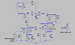
Ordinary Power Supplies used with toob applications always use a Low Pass Filter. With a bit of luck that removes the PS ripple/hum that occurs at the rectifier cathode. But allows the DC to pass.
The LP filter in Tizman's PS has a 3 db down point at 5.88 Hz. Then drops like a rock, ultimately at 24 db/octave. At the point where the output stage B+ is connected the ripple is almost non-existent.
There are no vacuum tube models in Electronic Workbench. But a simple work around uses power triodes as a substitute. That way the rectifiers simulate the real thing with a 3/2.s forward conduction curve.
Attachments
Thanks to everyone for your replies on the question of capacitor sizing. I started a new thread about just that question here..
https://www.diyaudio.com/forums/tubes-valves/372321-size-capacitor-node.html#post6654224
So far, I have received one response linking this article...
The Valve Wizard
This would appear on a first look to be similar to what we have looked at thus far. The relative lack of material on driver tube capacitance sizing may indicate that it is non critical. If that is the case, isn’t a 2.2 or 3.3 uF film capacitor better than a 22 or 33 uF electrolytic in that position when size is an issue?
I always use 3.3uf film cap for driver tube in my mono block build and I find it better sounding than a 33uf or 47uf or 100uf regular electrolytic. I always keep other Rs and Cs as small as possible.
Regards
I added 33 uF to each of the 2.2 uF caps on the 30s in the 6N1P-EV/KT120 amp, and it didn't seem to make any audible difference. I added capacitance to another amp's driver tube node, in this case a 6N1P-EV/KT120 single ended amp that had the 2.2 uF capacitor on the driver replaced with a 50 uF cap, and it sounded better with the small cap in that case.
It would seem that in the case of the 30/6P15P-EV amp, the concerns about small cap size on the driver tube node are unfounded. If this is the case, I'd rather use a smaller value film cap than a similarly sized higher value electrolytic in the same position. Hopefully someone will give us a definitive answer on the other thread I started on sizing driver tube caps.
With respect to "keep other Rs and Cs as small as possible", I always try to keep series resistance at a minimum in power supplies, but haven't thought about capacitance that way. I usually keep resistance low, and increase capacitance in order to achieve ripple goals.
Last edited:
It certainly seems like the input / driver tubes can function fine with small values.I always use 3.3uf film cap for driver tube in my mono block build and I find it better sounding than a 33uf or 47uf or 100uf regular electrolytic. I always keep other Rs and Cs as small as possible.
Regards
Have you compared the sound of a 3.3uf film with something in the 30uf to 50uf range that is also a film cap? I suspect the difference you've found may be simply because the larger values were electrolytics.
I think it's been well established that anytime you can replace an electrolytic with a film cap it's bound to be an improvement.
Can you think of any downside to using a larger film cap? My ears say no but I'm wondering if they might measure differently.
I ordered some 15uf DC Link (film) caps to use for the node that supplies the input tubes. As I mentioned, in my very brief experiment I didn't hear any issues with the 50uf motor run I'm using on the breadboard. In addition to trying the 0.1uf I also tried a 5uf motor run and didn't notice any audible differences.
Last edited:
The Enlightenment Part B
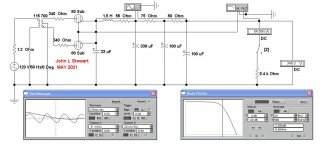
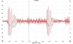
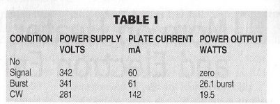
IT = CE………………………a very useful relation. So in these examples we can see the change of voltage on the final stage supply cap as program material is run. The supply cap in this case was 100 microF. There are two examples, one playing a CD of Peter Gabriel’s performance of Salisbury Hill, the other a 10 Watt, One KHz burst.
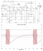
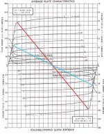
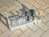
The amplifier in test is another of my brain storms, Class AB2 6V6’s built in 2001. I had a few objectives in mind, try Class AB2 & measure overhead available with a limited PS. Also try a differential cascade front end with output plate NFB to the upper grids of the cascade. The PP loadline is corrected for Class AB2, that is the steeper line.
Peter Gabriels performance results in a 12V drop on peaks (blue trace). Stuffing the numbers into the relation tells us the extra current supplied by the final cap for about 50 ms is ~24 mA.
The 10 watt bursts of One KHz look like only 3.7 mA. Need to check that, looks like the 10X probe was not dialed in.
The Burst Gate was built in about the same time.
IT = CE………………………a very useful relation. So in these examples we can see the change of voltage on the final stage supply cap as program material is run. The supply cap in this case was 100 microF. There are two examples, one playing a CD of Peter Gabriel’s performance of Salisbury Hill, the other a 10 Watt, One KHz burst.
The amplifier in test is another of my brain storms, Class AB2 6V6’s built in 2001. I had a few objectives in mind, try Class AB2 & measure overhead available with a limited PS. Also try a differential cascade front end with output plate NFB to the upper grids of the cascade. The PP loadline is corrected for Class AB2, that is the steeper line.
Peter Gabriels performance results in a 12V drop on peaks (blue trace). Stuffing the numbers into the relation tells us the extra current supplied by the final cap for about 50 ms is ~24 mA.
The 10 watt bursts of One KHz look like only 3.7 mA. Need to check that, looks like the 10X probe was not dialed in.
The Burst Gate was built in about the same time.
Attachments
-
 2013_03_21_001 Peter Gabriel Salsbury Hill.jpg77.9 KB · Views: 186
 -
 Schema And Burst Example 10W 20C.jpg90.8 KB · Views: 178
 -
 6V6GTA 14W 4 PushPull C 7W.jpg84.1 KB · Views: 178
 -
 PP 6V6 Cascode Front End Burst Results.jpg82.7 KB · Views: 171
 -
Amplifier Burst Testing.pdf589.7 KB · Views: 58
-
 026 Cascode Amp A.JPG898.7 KB · Views: 175
I always use 3.3uf film cap for driver tube in my mono block build and I find it better sounding than a 33uf or 47uf or 100uf regular electrolytic. I always keep other Rs and Cs as small as possible.
Regards
What is the final tube in those amplifiers? And how does that recommendation apply to a completely different output stage? Where did the use of very small final stage plate supply capacitors originate?
All these questions have importance in discovering why such a change would 'sound better'. And better than what & too who?
jhstewart9: I asked the question initially to see if I could find a method to work out a capacitance value for a given node. Several folks told me that the value chosen for the capacitor on the 30 tubes in my amp was too low at 2.2 uF. I asked how to work out an appropriate value, and Bill Brown linked the Loesch article. There has been some questioning of that article’s relevance and correctness, but I’m still waiting for someone else to tell me how to do it properly if that article is incorrect. Nothing yet....
Last edited:
I don't understand this "problem".
At "B+A" point al least 60dB PSRR (relative to B+) due to the PSU C-large R-C-large R-c filtrating.
The #30 anode current alteration is marginal versus output tube current, so "stressing" of PSU mainly due to the output.
The magnitude of "last C" of #30 anode circuit is almost negligible, the 1.5uF as good as 33uF.
If the B+ has 2Vpp hum, on the output only 36mVpp (shorted input), so the 35dB PSRR "thanks to" SE output.
“the 1.5uF as good as 33uF” is the case when listening. In fact the other amp to which I added capacitance to the driver power supply node sounded worse with the extra capacitance.
There was no hum from the B+ once the bias resistor bypass capacitor was added. This of course is a separate issue from the capacitor sizing.
Dear Fla, earlier you wrote:
''It certainly seems like the input / driver tubes can function fine with small values.
Have you compared the sound of a 3.3uf film with something in the 30uf to 50uf range
that is also a film cap? I suspect the difference you've found may be simply because
the larger values were electrolytics.
I think it's been well established that anytime you can replace an electrolytic with a
film cap it's bound to be an improvement.
Can you think of any downside to using a larger film cap? My ears say no but I'm
wondering if they might measure differently.''
If you have a analog multimeter pls check charging and discharging pattern of the capacitors. Usually charging is smooth discharge is not. Yes, in general Film caps are better.
Tizman.....we are growing older in this thread alone, but it is a good exercise. Every design is optimization, my take on PS for 2 stage SE tube amp with tube rectifier where driver draws 5-15 mAmp and output tube draws 35-70 mAmp current is:
CLCRC current tap for 35-70mAmp output tube
and
RCRC for 5-15 mAmp driver tube i.e.
For output tube
C L C R C
1-2uf film 5-10H low dcr 100-200uf 100-200R 50-100uf
and
For driver tube
R C R C
as small possible 33-47uf as small possible 2.2-10uf film
The above is inexpensive and good sounding. IT SEEMS LIKE LOW PASS/HIGH PASS, FREQUENCY RESP not a problem that I can hear in this configuration. Quality of LCR is very important and oversizing resistor is good because heated resistors make noise/distortions.
We can improve the above PS with CLCLCRCRC and all film/oil/motor run caps.
Regards
''Have you compared the sound of a 3.3uf film with something in the 30uf to 50uf range
that is also a film cap? I suspect the difference you've found may be simply because
the larger values were electrolytics.''
Yes and no. Usually charging and discharging time and the smoothness for these
functions are better for smaller caps, be it elec or film.
Regards
that is also a film cap? I suspect the difference you've found may be simply because
the larger values were electrolytics.''
Yes and no. Usually charging and discharging time and the smoothness for these
functions are better for smaller caps, be it elec or film.
Regards
All I have is a digital meter. When I experimented with the tiny .1uf cap I did connect the meter to the cap and watch it during startup and later with music playing. I was measuring voltage, though, not current, since increases in current draw would lead to a decrease in voltage. And I was measuring the cap that supplies the input tube, not the B+ cap that supplies the outputs.If you have a analog multimeter pls check charging and discharging pattern of the capacitors. Usually charging is smooth discharge is not. Yes, in general Film caps are better.
I saw the same pattern with all the cap sizes I tried (.1uf, 5uf, 50uf) during startup and with music playing regardless of cap size. With music playing the voltage only varied a tiny bit. This variation was in the range of .1v to .2v but it didn't seem to correspond to the music so I figured it was most likely due to small variations in wall voltage. Perhaps an analog meter would be better or some other more sophisticated equipment.
The graph that John Stewart posted seems to be the most accurate and revealing information that's been presented in terms of showing how much charge a music signal is actually drawing from a supply cap. I'm not sure how he measured it or if it's a simulation. But, as with the Loesch article, the graph shows the effect on the B+ node that supplies the power tubes. I would expect the results to be quite different if the input tube supply cap was being measured.
I've never spent much time trying to determine an "optimal" value for any particular PS cap. I've always figured that having a bit more capacitance in reserve is a good idea but just don't go so large that it has a negative effect.
So I just try to strike a vague balance. I doubt I could hear the difference between "ideal" and "close enough".
Calculating the minute details may be an interesting technical exercise for an EE or someone who enjoys that aspect of design, but my brain doesn't work well in that realm.
Of course, smaller caps recharge more quickly than large ones. If you play around with the cap charging calculator I posted, you can see the details.Yes and no. Usually charging and discharging time and the smoothness for these functions are better for smaller caps, be it elec or film.
So I figure the balancing act is to use a cap that recharges relatively quickly but is not so small that it ever runs out of current. Of course, this assumes that the ripple is acceptably low.
That would suggest that the under 5uf caps that you and Tizman are using would be good choices to supply the input tube. But, as I said, I couldn't hear any difference between 5uf and 50uf when both were film caps.
- Home
- Amplifiers
- Tubes / Valves
- DHT driver for triode wired SE EL84, 6V6 or EL34