6A3sUMMER: I will try using LEDs to bias the 30 tubes. I believe that the Coleman regulators are not supposed to be grounded. Another option would be to use the Coleman regulators with filament bias. I’m not sure if that would result in a reduction of noise though.
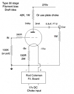
I've tried SIC diodes but I find filament bias smoother. You need a very clean supply to Rod's regs, which are floating and only grounded through the cathode resistor. I use choke input for the filament supplies. Choke only needs to be 100mA so plenty of choice up to 10H. Attached a specimen circuit. A plate choke would be best, like Lundahl LL1667, LL1668. Even a Hammond 157G, 155C or 156C though the latter two can be prone to hum pickup from other magnetic components. You shouldn't need a cathode bypass with a plate choke with good inductance. If you ever have to use a cathode bypass, use a DC Link capacitor. The best I've tried by some way.
Attachments
Last edited:
andyjevans: Thanks for the schematic. I will try another amp with filament bias and a plate choke as I have a pair of the 156C on hand. I also want to try the Bartola Gyrator on the plates.
I can’t wait to get back listening to the 30/6P15P-Ev amp. Even with its flaws, it is the most real sounding and enjoyable amplifier in my stable. I don’t want to do anything other than listen to it for a while.
I can’t wait to get back listening to the 30/6P15P-Ev amp. Even with its flaws, it is the most real sounding and enjoyable amplifier in my stable. I don’t want to do anything other than listen to it for a while.
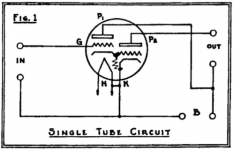
I don't see how a triode configured as a cathode follower that's directly coupled to another triode can be seen as a tetrode. But, then, I'm not the sharpest knife in the drawer. No doubt others will have a more informed answer regarding the technical aspects.Is the 6N6G operated as a tetrode in FlaCharlie’s schematic attached above? As drawn by FlaCharlie, the power element looks like a triode. In the data sheet the power element has a second grid connected to the first grid and to the cathode. On the 6N6G power element, what is the part of the tube that looks like another grid element between the two connected grids and the cathode?
The developer of the tube, Triad, seems to have dubbed the design as a "Triadyne", although the name doesn't seem to have caught on. The data sheet clearly describes it, and depicts it, as a dual triode.
For my schematic I had to draw my own version since, not surprisingly, I couldn't find one. My diagram is essentially the same as the one in their original data sheet for the 6B5, which was the first version of this tube. Since it's a small space I simply omitted the internal bias resistor. Triad also omits the resistor from less detailed diagrams in their data sheets.
I've attached the original Triad diagram from their extremely detailed data sheet. I think your confusion is based on the diagram shown in a data sheet published by a different manufacturer. It seems to me that the Triad data sheet should be considered the definitive version, since they invented the tube.
A survey of the data sheets published by other manufacturers reveal that there was no consensus on how to draw the internals of these tubes. While I find that to be curious, I'm more interested in more practical aspects such as the basic implementation of the tube and how it sounds.
While it's not totally relevant to this thread, which has been focussed on using a SE output configuration, I've used the 6N6G in PP for about 10 wpc output, although I used an indirectly heated input / phase inverter (5751).
I haven't studied it much, but the Triad data sheet also describes a "high efficiency PP" mode which produces 20 wpc at 5% distortion. And, though not mentioned in the data sheet, I assume it would be possible to use a PSE configuration using either the "normal" operating points or the "high efficiency" ones.
Although the drive requirements are significantly higher, perhaps DHT input tubes would offer the same sonic advantages we've experienced with SE outputs in such designs.
That's probably best left for a future thread. I offer it up only as food for thought since the desire for higher power output has been mentioned previously.
Attachments
Last edited:
The problem cured by application of a bypass cap across the 30 bias resistor is not as apparent for the same conditions on a 26 vers. The bias resistor is much less resistance for the 26, the interfering voltage developed across it is much less. The gain of the 30 & 26 are almost the same, the resulting noise at the amp output terminals is less for the 26 amp.")
The problem cured by application of a bypass cap across the 30 bias resistor is not as apparent for the same conditions on a 26 vers. The bias resistor is much less resistance for the 26, the interfering voltage developed across it is much less. The gain of the 30 & 26 are almost the same, the resulting noise at the amp output terminals is less for the 26 amp.
jhstewart9: I’m hoping that the issue is indeed with the power transformer, as I have a few that I could swap out for it. The capacitor on the 30 tube that you suggested greatly reduced the hum to to tolerable levels, but it would be great to not have the base problem and have that capacitor be optional rather than required.
#30 filament current is 60mA.
For example -one of recommended- bias point is 135V, 3mA, -9V.
If you use 150R as filament bias resistor, the 60mA current trough it results 9V bias.
Because this filament bias resistor is too large, I recommend to use few hundred uF capacitor paralleling.
For example -one of recommended- bias point is 135V, 3mA, -9V.
If you use 150R as filament bias resistor, the 60mA current trough it results 9V bias.
Because this filament bias resistor is too large, I recommend to use few hundred uF capacitor paralleling.
#30 filament current is 60mA. For example -one of recommended- bias point is 135V, 3mA, -9V. If you use 150R as filament bias resistor, the 60mA current trough it results 9V bias.Because this filament bias resistor is too large, I recommend to use few hundred uF capacitor paralleling.
Yes, I used this "book" operating point in my suggested circuit. But I find that 150R doesn't need a bypass if you have good inductance on your plate choke. My plate chokes are 150H or more, and they cope fine with resistor values up to around 250R. Lower is better of course, but I'm not a fan of bypasses however nice the DC Link caps sound.
Another recommended operation point for the 30 is 90v, 2.5mA, -4.5v. This would allow you to cut the bias resistor value in half to 75R.#30 filament current is 60mA.
For example -one of recommended- bias point is 135V, 3mA, -9V.
If you use 150R as filament bias resistor, the 60mA current trough it results 9V bias.
Because this filament bias resistor is too large, I recommend to use few hundred uF capacitor paralleling.
In your opinion, would this allow him to eliminate the bypass cap?
Another recommended operation point for the 30 is 90v, 2.5mA, -4.5v. This would allow you to cut the bias resistor value in half to 75R. In your opinion, would this allow him to eliminate the bypass cap?
As you say, you can play around with operating points and lower the resistor value. It all depends on the inductance of your plate chokes. The LL1667/8 should be fine.
Another way to do it is change the tube. The VT-67 is a type 30 with twice the filament current. So for 9v bias you'd have your 75R cathode resistor. Less microphonic as well.
If you compare -any of them- to 10k internal resistance, it's -almost- negligible ... but across this resistor flowing the filament current.
If it's not clean enough (or the environment not enough shielded), the hum/noise/RF (use exclusively non inductive resistor!) directly modulating the tube's bias.
The greater the resistance/impedance, the greater a modulation.
If it's not clean enough (or the environment not enough shielded), the hum/noise/RF (use exclusively non inductive resistor!) directly modulating the tube's bias.
The greater the resistance/impedance, the greater a modulation.
If you compare -any of them- to 10k internal resistance, it's -almost- negligible ... but across this resistor flowing the filament current. If it's not clean enough (or the environment not enough shielded), the hum/noise/RF (use exclusively non inductive resistor!) directly modulating the tube's bias. The greater the resistance/impedance, the greater a modulation.
Good point! Clean filament current is pretty central.
An answer to the buzzy/hum problem.
As per jhstewart’s suggestion, I grounded the core of the filament transformer and I lifted one leg on both cathode resistor bypass capacitors. The result is a much reduced level of hum even with the cathode resistor bypass capacitor out of the circuit. Unfortunately, the cathode resistor bypass capacitors will still be required given the residual hum that is left over. I would think that when using speakers of more normal sensitivity, the residual hum would not be very audible. With my speakers, it is just audible at the listening position, and obviously audible at the speaker.
This result would appear to indicate that the problem is with the filament power transformer coupling mains noise through the filament circuit. It may be the case that the series of Hammond transformers that I am using is not a good choice because it is a PCB mount transformer that is not mounted to the chassis and therefore not grounded to the chassis. Adding a DIY grounding wire greatly improved, but did not eliminate the problem. This is why none of the other substantial troubleshooting I did had a positive outcome. Given my issues, it is probably advisable to only use transformers that are made in a way that allows their core to be grounded to the chassis when implementing Coleman regulators.
With the cathode resistor bypass capacitors reconnected, the ground wire makes no difference to the residual hum left over at the speakers. It seems that grounding the PT or using the cathode resistor bypass capacitor have the same result, and that there is no improvement when using both at the same time. I will test a bit more to confirm this.
Last edited:
I tested some more, and it is quieter with both the filament PT core grounded and the cathode resistor bypassed with a capacitor. The capacitors improved the problem the most, with the amp being only a little bit quieter with both the capacitors and the filament PT ground connected as compared to just having the capacitors connected. The PT core being grounded greatly reduced the hum, but not as much as the capacitors, and not enough on its own without the capacitors.
If you compare -any of them- to 10k internal resistance, it's -almost- negligible ... but across this resistor flowing the filament current.
If it's not clean enough (or the environment not enough shielded), the hum/noise/RF (use exclusively non inductive resistor!) directly modulating the tube's bias.
The greater the resistance/impedance, the greater a modulation.
euro21: When you say “use exclusively non inductive resistor”, where do you mean? The cathode bias resistor?
hello Tiz, Yes, perhaps the Hammond is not as good as it appears.
Attempts to Ground the core can only partly succeed, since the core is in laminations, designed to break up eddy currents.
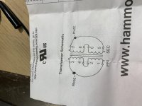
If you have a capacitance function on your DMM, you may be able to get a reading of capacitance from PRI-SEC windings. 50-70pF is usually good enough for filament supplies; but the older low-current filamentary triodes are more susceptible to all kinds of noise pickup, so it could be that a better trafo is needed anyway.
If the bypass cap is still needed, even with these, moving to LED or diode bias might be better (the diodes can be selected to approach the signal-impedance of an electrolytic cap). Or use grid bias, and connect the FIL+ terminal directly to ground.
The surest way to eliminate this kind of (common-mode) noise: a transformer with an electrostatic shield. The Antek AS-series is an Audio Grade transformer, and the 50VA or bigger versions have a shield. Other Audio-grade trafos made by Canterbury Windings and Air-Link in the UK, and Toroidy in Poland have shields and are designed for reduced flux in the core, which is also very helpful. R-core trafos are also likely to be good.
But, Beware: If you still have a steel chassis, that may be confusing matters.
Attempts to Ground the core can only partly succeed, since the core is in laminations, designed to break up eddy currents.
If you have a capacitance function on your DMM, you may be able to get a reading of capacitance from PRI-SEC windings. 50-70pF is usually good enough for filament supplies; but the older low-current filamentary triodes are more susceptible to all kinds of noise pickup, so it could be that a better trafo is needed anyway.
If the bypass cap is still needed, even with these, moving to LED or diode bias might be better (the diodes can be selected to approach the signal-impedance of an electrolytic cap). Or use grid bias, and connect the FIL+ terminal directly to ground.
The surest way to eliminate this kind of (common-mode) noise: a transformer with an electrostatic shield. The Antek AS-series is an Audio Grade transformer, and the 50VA or bigger versions have a shield. Other Audio-grade trafos made by Canterbury Windings and Air-Link in the UK, and Toroidy in Poland have shields and are designed for reduced flux in the core, which is also very helpful. R-core trafos are also likely to be good.
But, Beware: If you still have a steel chassis, that may be confusing matters.
euro21: When you say “use exclusively non inductive resistor”, where do you mean? The cathode bias resistor?
Yes.
Inductive resistors act as antenna, producing more or less noise/hum.
hello Tiz, Yes, perhaps the Hammond is not as good as it appears.
Attempts to Ground the core can only partly succeed, since the core is in laminations, designed to break up eddy currents.
If you have a capacitance function on your DMM, you may be able to get a reading of capacitance from PRI-SEC windings. 50-70pF is usually good enough for filament supplies; but the older low-current filamentary triodes are more susceptible to all kinds of noise pickup, so it could be that a better trafo is needed anyway.
If the bypass cap is still needed, even with these, moving to LED or diode bias might be better (the diodes can be selected to approach the signal-impedance of an electrolytic cap). Or use grid bias, and connect the FIL+ terminal directly to ground.
The surest way to eliminate this kind of (common-mode) noise: a transformer with an electrostatic shield. The Antek AS-series is an Audio Grade transformer, and the 50VA or bigger versions have a shield. Other Audio-grade trafos made by Canterbury Windings and Air-Link in the UK, and Toroidy in Poland have shields and are designed for reduced flux in the core, which is also very helpful. R-core trafos are also likely to be good.
But, Beware: If you still have a steel chassis, that may be confusing matters.
Rod: How do I properly measure capacitance from primary to secondary on the Hammond 229B16? It has two primaries and two secondaries. If I attach the DMM probes as indicated in the attached photo, I get 36 pF.
Attachments
- Home
- Amplifiers
- Tubes / Valves
- DHT driver for triode wired SE EL84, 6V6 or EL34