About 10 years ago I purchased PMC EB1i loudspeakers for use with solid state amplifiers. These were industrial AB class amplifiers, and selfmade single-ended class A amplifiers, some of which I discussed on this forum. After some time, I began to try to connect tube amplifiers to these loudspeakers, in particular, I purchased a NEM A300SE single-ended tube amplifier. While I liked the sound with tube amplifiers more, it was obvious that with these large loudspeakers, tube amplifiers did not provide the ability to sound full at low frequencies. So I started trying single-ended designs with larger output tubes. First, with GM70 output tubes, then I assembled output monoblocks with GU48 tubes (a complete analogue of 833, but with a metal anode). The impressions from the evolution of output tubes are such that the more power dissipated at the anode, the more confident and full the system with these loudspeakers sounds. The output impedances of all three tube amplifier options were 0.65 ohms with the 300B tubes (special low Rout version), 0.8 ohms with the GM70, and 0.8 ohms with the GU48. The sound impressions increased with the increase in the power dissipated at the anode. Tube PP tube amplifiers did not fit into my preferences, the sound was not as interesting as with single-ended amplifiers. Since the NEM A300SE amplifier was little used, I converted it into a driver unit. To do this, all layers of the secondary winding were connected in series (instead of parallel connection, the heater voltage for 300B was rectified, the ripple of the anode voltage was also additionally suppressed. As a result, now there are two independent driver units, and two independent sets of output units. From listening experience, I can say, that for full sounding it is important to reduce the output impedance of the driver units (but not by using cathode followers). Both units use interstage transformers at the output. One driver unit has UO186 (YO186) tubes at the output and an interstage transformers with 2: 1 step down. Another driver unit is with 300B tubes at the output and a step-down interstage transformer 3 : 1 (this ratio has occured when the sections of the secondary winding were connected in series.) Now a completely harmonious sounding system has been created, and most importantly, all the attractiveness of the sound of single-ended tube amplifiers has been preserved.

Last edited by a moderator:

The anode power supply in the output units on the gm70 and gu48 is organized differently. In the case of gm70 (1100 volts), emitter followers on IGBT BUP314 transistors are used to smooth out ripples. For gu48 (1950 volts), the usual CLC circuit was used (100μF - 20H - 200μF, film capacitors K75-24, each 100μF x 2000 volts). Shunts made of silver-mica capacitors were installed directly on the tube panels. The anode voltage rectifiers use Qspeed series 600 volt 5 ampere diodes. For sound, both approaches give a fairly close result.
Gm70 filament heaters are made with rectifiers based on germanium diodes D305 (50 volts, 10 A).
Gu48 filament heaters are made using switching power supplies, after which RC circuits are installed to suppress high-frequency noise. Three 0.1 Ohm wire resistors connected in parallel come to each filament contact, and between the filament contacts there are three capacitors connected in parallel - silver-mica, film, and electrolytic at 3300 microfarads. The noise reduction on the filament legs was checked using an oscilloscope.
Gm70 tubes were produced in three versions: 1) with a metal anode (their production was discontinued in 1963); 2) with a graphite anode; 3) with a copper anode. Tubes 2) and 3) were produced until the 1980s.
Tubes 1) are the best in sound, except for the differences in the material of the anode, they have a more durable mechanical structure, the anode part is mounted on four supports, but the dissipation power at the anode is not more than 90-100W. In tubes 2) and 3), the anode part is installed on two supports, but the dissipation power can reach the passport values of 125W.
Tubes 1) in NOS state do not exist now, only used ones. Also, all GM70s require more secure packaging for mail delivery. During shipment, the filaments may break off, or springs fly off, which create tension on the filaments. I was very upset when two tubes 1), bought from a seller in Singapore, came with broken filament. Many expectations and plans were destroyed. Only after a couple of years I managed to buy similar tubes from another seller. Therefore, it is best not to consider tubes 1) for the application at all.
Tubes 2) cost 15-50usd (the more expensive ones are by Photon plant), and tubes 3) cost 70-100usd. They can be used, taking into account the high prices for 845 tubes produced in China. And in terms of the power dissipated at the anode, 845 tubes are significantly inferior to GM70.
Last edited:
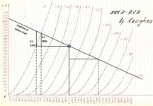
It should also be noted that the desire to lower output impedance, for better matching with loudspeakers, runs counter to the desire to increase the output power. For the gm70, output transformer with a turns ratio of 50:1 was used, while the maximum output power in class A1 was reduced to 18 W with an output impedance of 0.8 Ohm. For example, the maximum output power can be nearly doubled by using a 35: 1 turn ratio, but this increases the output impedance to approximately 1.4 ohms. Manufacturers of amplifiers based on gm70 usually use the second option, since 18W output power does not attract potential buyers.
In monoblocks on gu48, the output transformer has a turns ratio 72: 1. The output power is about 50W, but at the same time we have to go a little into class A2, with grid currents. Due to the high internal impedance of gu48 (about 4 kΩ), making an output transformer is a rather difficult engineering task. I came to a compromise and ordered transformers in Israel (several times cheaper than Monolith Magnetics).
In monoblocks on gu48, the output transformer has a turns ratio 72: 1. The output power is about 50W, but at the same time we have to go a little into class A2, with grid currents. Due to the high internal impedance of gu48 (about 4 kΩ), making an output transformer is a rather difficult engineering task. I came to a compromise and ordered transformers in Israel (several times cheaper than Monolith Magnetics).
One of the pre-amplifiers, as mentioned above, is an upgraded NEM A300SE amplifier. Another preamplifier is a two-stage circuit, I describe it briefly here. At the input, a stereo TKD step attenuator with 3 kΩ total resistance is used. The low resistance of the attenuator allows to increased the cutoff frequency, determined by the input capacitance of first stage tube . Also, to reduce the input capacitance, the first tube is a pentode in pentode connection (6zh6s, which is a complete analogue of the English Z62 pentode). This particular pentode was chosen because it was mentioned for its sound on the forums, compared to other pentodes. However, this is a matter of taste. This solution is a good option to get the voltage gain of the first stage around 100, while the input capacitance of the first stage is only about 10pF. It is absolutely unacceptable to use triodes with a high gain in the first stage, for example, like 6SL7, due to the large Miller capacitance, except for the case when the frequency response drop is compensated by the use of feedback. If one measures frequency response of a separate 6SL7 stage, even if the signal is fed into the grid directly from a generator with output impedance 50 ohms, visible drop in frequency response begins already at 10 kHz.
In the anode of input pentode I use 15 kΩ resistor , and it determines the output resistance of the first stage. Therefore, for the second stage (driver tube) it is necessary to use a low gain triode to reduce the Miller capacitance. I used YO186 triode, although 2A3 and 6B4G will also provide low input capacitance. The driver tube is loaded by 2:1 interstage transformer to reduce the driver output impedance and improve sound dynamics. It should be borne in mind, that gu48 output tube has voltage gain of more than 30, and respectively it has large input capacitance. Therefore, for gu48, the driver on 300B tube with 3:1 step-down interstage transformer, as happened with the NEM A300SE amplifier, is not redundant.
In the anode of input pentode I use 15 kΩ resistor , and it determines the output resistance of the first stage. Therefore, for the second stage (driver tube) it is necessary to use a low gain triode to reduce the Miller capacitance. I used YO186 triode, although 2A3 and 6B4G will also provide low input capacitance. The driver tube is loaded by 2:1 interstage transformer to reduce the driver output impedance and improve sound dynamics. It should be borne in mind, that gu48 output tube has voltage gain of more than 30, and respectively it has large input capacitance. Therefore, for gu48, the driver on 300B tube with 3:1 step-down interstage transformer, as happened with the NEM A300SE amplifier, is not redundant.
Last edited:
Stunning valve amps thank you for sharing your information on the design choices.
I had not heard of NEM before and had to search for their website.
I hope you continue to find sources for the tubes, and as you like it more than 845's it must sound fantastic.
Does sourcing transformers and HV capacitors cause you any issue in Tashkent?
It takes a brave man to work with 1100 volts dc valve supplies.
Stay safe from covid and HT.
Hello, raymondj. HV capacitors I've found NOS in Tashkent, but they are in production still, by this manufacture in Russia
http://www.elcod.spb.ru/catalog/k75-40.pdf
Tubes gu48 I have got NOS in Tashkent, they are with metal plate. 833 tubes are produced now in China, but with graphite plate. Metal plate is better for sound. Metal plate of gu48 becomes red at normal operation. This is no problem, since plate material is thicker than usual. And plate material serves as a getter.
Power supplies toroidal transformers can be made in Tashkent. The output transformers also can be made, but I have preferred to order them abroad (HiB core, better wire quality). Chokes are made in Tashkent.
As I have mentioned in #3, manufacturers usually put the output power on the top in their designes. From the review of WAVAC amplifier in Stereophile, "The SH-833's output impedance was on the high side, at 5 ohms from the 8 ohm transformer tap and 2.6 ohms from the 4 ohm tap." At this, stated output power is 150W. I wonder, is this situation really preferable to users? What real world speakers sound good with very low damping factor?
Here is the Home site of NEM. A300SE is not in their catalog now.
Amplifiers - NEM
But it is sold still by German partner of NEM
NEM A300SE Röhrenvollverstärker
Amplifiers - NEM
But it is sold still by German partner of NEM
NEM A300SE Röhrenvollverstärker
http://www.monolithmagnetics.com/sites/default/files/wards-blog_0.pdf
In this article one can find many info about possible schematics for driving 833 tube.
In this article one can find many info about possible schematics for driving 833 tube.
It is a person in Israel, whicn makes his small business via Russian forums. I just have checked, can not find his email. I could ask him, and get an email, if he will agree. He buys metal cores at Eilor plant in Israel (HiB, Amorphous, Nano). And he is doing himself calculations and design.
It should be noted, that 833 tube was designed to work with grid currents and high plate currents, and also with relatively high voltage gain. The tube grid is located quite close to the cathode, and even small spread in the geomeric location of the grid relative to the cathode can significantly affect the plate characteristics of these tubes, when they are used with negative grid offsets, without grid currents. For example, a user bought two tubes, and with available 1900 volt plate power supply, by selecting a cathode resistor in a cascade with auto-bias, set the plate current to 160 mA. And resulting operating point is close to the values in datasheet. Then he changes the tube to another, and with the second tube he has to reduce the cathode resistor by almost half (correspondingly reduce the negative grid bias) in order to obtain the same plate current 160 mA. The user can assume, that the second tube was sold to him with a depleted resource, with reduced emission. In fact, this is the scatter of the geometric parameters of the grid and cathode. I had such a situation when all the tubes were taken out of sealed boxes. Then, by selection, we managed to find a tube close to the first one. Another forum member had a similar situation when he ordered a pair of 833 tubes in China. Therefore, for the possible purchase of gu48 or 833 tubes, it is very important, if the seller has ability to measure plate currents in modes close to the intended operating point. This will certainly add some cost, but better not to risk buying 833 tubes blindly on ebay.
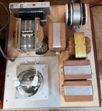
Hello, Matt. The core of this toroidal transformer was epoxy-glued from three standard cores with a power of 150 watts each. The result is such a tall core and non-usual shape of the toroidal transformer. An AC voltage of 1470 volts is generated on the secondary winding of this transformer, which goes to the gu48 plate voltage rectifier. The toroidal transformer is fixed in such a position as to minimize the penetration of the external magnetic field generated by it into the output transformer. In earlier designs, when the power transformers were not properly positioned relative to the output transformer, hum due to induced external magnetic fields occurred.VladimirK, that's a very nice looking build. Interesting way to mount the, I presume, two toroidal transformers. What are they for? Cheers
Matt
- Home
- Amplifiers
- Tubes / Valves
- Tube amplifiers with PMC EB1i speakers