Have you tested your diac-based protection with a oscilloscope?
I have observed it with an oscilloscope,
")
Quote:
Originally Posted by pcan
Have you tested your diac-based protection with a oscilloscope?
I have observed it with an oscilloscope
--------------------------------------------------
What is the observed 'it thing' you observed?
Shew us what it looks like coming out of your amplifier as it operates on an overload signal. Most of us know what a DIAC does & what the signal looks like during normal operation in its intended circuits.
Quote:
Originally Posted by pcan https://www.diyaudio.com/forums/tub...-using-6sn7-6sl7-post6471848.html#post6471848
Have you tested your diac-based protection with a oscilloscope?
I have observed it with an oscilloscope
--------------------------------------------------
What is the observed 'it thing' you observed?
Shew us what it looks like coming out of your amplifier as it operates on an overload signal. Most of us know what a DIAC does & what the signal looks like during normal operation in its intended circuits.
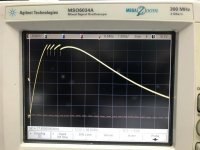
Here attached with the waveform. You could observe that there are 4 protections at the output after the start-up time.
Attachments
The breakover voltage of the DB3 is given as 28-36 volts on the Spec Sheet. So if exceeded a step of that size would be applied to the gain control. Depending on the gain control setting a step function goes to whatever speaker system is connected. Could be damage.
As I mentioned before, this DB3 does not serve as a protection to speakers. Instead, it protects the input. However, DB3 certainly could also protect the speakers to some extent as the peak maximum is around peak-to-peak 5V at protection moment. I believe it is much better than you add nothing as at least the voltage could be kept under 30V.
Usually, gain control could not avoid the peak at Tube Amplifiers, under many common situations the over-voltage will occur:
Firstly, the over-voltage occurs at the start-up time.
Secondly, some of the power sockets loose or have bad-contact.
Thirdly, when the signal sockets loose.
Fourthly, the Electrostatic discharge (ESD).
Fifth, the noise generated by the power, the inappropriate use of equipment........
That's a interesting circuit. If I correctly understood your measurement, the input of the power amplifier does see 4 narrow pulses with 5V peak-to-peak amplitude, clustered in a 20ms window. That's a step forward compared to the situation without the DB3 diac, because I've seen 35V rated coupling capacitor at the input of many chip amps, and they may be damaged if some protection is missing. But I think that the goal should be to also remove those spikes. Could you do a little further test? Try connecting a 24V zener diode in parallel to the DB3 diode. Measure the output with and without the DB3.
That's a interesting circuit. If I correctly understood your measurement, the input of the power amplifier does see 4 narrow pulses with 5V peak-to-peak amplitude, clustered in a 20ms window. That's a step forward compared to the situation without the DB3 diac, because I've seen 35V rated coupling capacitor at the input of many chip amps, and they may be damaged if some protection is missing. But I think that the goal should be to also remove those spikes. Could you do a little further test? Try connecting a 24V zener diode in parallel to the DB3 diode. Measure the output with and without the DB3.
Your suggestions is actually not necessary to be carried out as all of us understand well that this is a straight line. As what I have mentioned before, if you do not satisfy with the over-voltage, you could choose a zener with lower voltage instead. For the reason why I did not use a zener is that there is a hidden problem when using zener. Protect a circuit, the very basic function is to protect itself. However the zener current is too low(around 100mA), for DB3 which is around 2A. That is 20 times larger than zener's. Zener would be much easier to be damaged at the protection moment. Therefore, choosing a DB3 is simple and enough.
If you really hope to decrease the voltage, I suggest "TVS".
As observed from the two schematics I previously posted, why did I apply a voltage doubler rectifier circuit but not a bridge rectifier one?
The answer to this question is:I want to reduce the frequency of power supply noise "humming" form 120HZ to 60Hz, made noise easy to control and lower, and use max W of the transformer
The answer to this question is:I want to reduce the frequency of power supply noise "humming" form 120HZ to 60Hz, made noise easy to control and lower, and use max W of the transformer
Last edited:
As observed from the two schematics I previously posted, why did I apply a voltage doubler rectifier circuit but not a bridge rectifier one?
That is a half-wave doubler in your PS. The ripple frequency is the same as the line frequency. The RC filter section is 6 db less effective than it would be if a full wave doubler had been used.
If the filter section had been LC (its not), it would be 12 db more effective with a full wave doubler than with a half wave doubler.
Half wave doubler only if there is no other way!
As I mentioned before, this DB3 does not serve as a protection to speakers. Instead, it protects the input. However, DB3 certainly could also protect the speakers to some extent as the peak maximum is around peak-to-peak 5V at protection moment. I believe it is much better than you add nothing as at least the voltage could be kept under 30V.
The circuit M7 on page one of the thread shews the DB3 at the output of the preamp, not the input.
The circuit M7
on page one of the thread shews the DB3 at the output of the preamp, not the input.As observed from the two schematics I previously posted, why did I apply a voltage doubler rectifier circuit but not a bridge rectifier one?
The answer to this question is:I want to reduce the frequency of power supply noise "humming" form 120HZ to 60Hz, made noise easy to control and lower, and use max W of the transformer
Lower frequency is not beneficial. The noise is neither lower, nor easier to control. As jhstewart said, full wave doublers make more effective use of both RC and LC filters.
Using the maximum power of the transformer is not a benefit of this scheme either. Spend some time with a simulation or scope or calculations before you attempt to play professor.
As observed from the two schematics I previously posted, why did I apply a voltage doubler rectifier circuit but not a bridge rectifier one?
That is a half-wave doubler in your PS. The ripple frequency is the same as the line frequency. The RC filter section is 6 db less effective than it would be if a full wave doubler had been used.
If the filter section had been LC (its not), it would be 12 db more effective with a full wave doubler than with a half wave doubler.
Half wave doubler only if there is no other way!
Yes, half-wave rectifier is the same as the line frequency(50 or 60Hz),full-wave or bridge rectifier is the double the line frequency (100 or 120HZ),half-wave at the filter section will worst than full-wave, But only need to increase the Capacitance of filters can be solved perfectly,There are many ways to consider the propagation of power noise not only at the B+,The following factors is full-wave will worst than half-wave:
1,Transmission between wires
2,Low frequency transmission ability is weak
3,People are already less sensitive to low frequencies
4,Positioning of electronic parts
5,Ground wire
6,Ground wire to chassis Ground
7,.........
So I believe the low frequency is very advantageous
Bunk!!
Increasing the capacitance increases the peak current applied to the PT. It is the RMS currents that cook transformers, not the average current. Looks like you have never heard of transformer winding utility factor, a measure of currents both AC & DC in the transformer windings, depending on whether the load is full wave of half wave, capacitor input to filter or choke, resister load or charging a battery. Better go back to school for a while, You have failed the power conversion in power systems test. The losses during conversion from AC to DC appear as heat. And even more losses in the core, both hysteresis & eddy currents, especially those caused by the harmonics caused by the AC to DC conversion.
Increasing the capacitance increases the peak current applied to the PT. It is the RMS currents that cook transformers, not the average current. Looks like you have never heard of transformer winding utility factor, a measure of currents both AC & DC in the transformer windings, depending on whether the load is full wave of half wave, capacitor input to filter or choke, resister load or charging a battery. Better go back to school for a while, You have failed the power conversion in power systems test. The losses during conversion from AC to DC appear as heat. And even more losses in the core, both hysteresis & eddy currents, especially those caused by the harmonics caused by the AC to DC conversion.
- Status
- This old topic is closed. If you want to reopen this topic, contact a moderator using the "Report Post" button.
- Home
- Amplifiers
- Tubes / Valves
- DIY Marantz M7 using 6SN7 and 6SL7