I have a quick question ... i am afraid a silly one.
If i take a normal tube preamp design for instance an anode follower and i take the signal instead out of the cathode of the tube will i get a cathode follower ?
with a dc blocking cap of course.
Because this is the case with bjt ... if i take the signal from the collector i have Vgain .. instead if i connect the emitter i will have a buffer.
I mean ... is the collector like a plate and the emitter like a catode ? i am quite confused
Anyway i am very willing to try a buffer now. Thanks again.
You also move the load from the plate to the cathode. Usually a cathode follower has it's plate connected to B+ directly, and the "plate resistor" gets put under the cathode instead.
What's your reason for wanting to use a 150V B+? A 220V isolation transformer will give you 300VDC when rectified - perfect for most signal tubes.
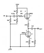
Here's a schematic of a buffer I built for a member on here named Kingsley. The bottom 6N8S replaces the normal resistor load for better linearity and it also moves the heat out of the chassis (if you mount the tubes on top like I do).
Attachments
You also move the load from the plate to the cathode. Usually a cathode follower has it's plate connected to B+ directly, and the "plate resistor" gets put under the cathode instead.
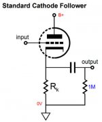
Thanks again. I think i have found the most basic schematic and i am attaching it. I will study cathode followers for sure. They could be the best option for me indeed.
i see. But i can find quite easily and i have already a step up transformer from US voltage to EU voltage that i can use reversed that can provide me 110VAC and 154V after rectificationWhat's your reason for wanting to use a 150V B+? A 220V isolation transformer will give you 300VDC when rectified - perfect for most signal tubes

I have a psycological issue with high voltages ,,, anyway i would like to try a dc dc converter with high voltage out
If i am not wrong the PSRR of a cathode follower can be quite good ?
that is also a nice advantage
Here's a schematic of a buffer I built for a member on here named Kingsley. The bottom 6N8S replaces the normal resistor load for better linearity and it also moves the heat out of the chassis (if you mount the tubes on top like I do)
Thank you very much again. But i still have a crazy idea to modify something that i have already at hand and make a very basic CF with these 6N3 tubes
or maybe 6922 or 12bh7 given that i can find easily converting sockets
I will try to draw down the schematic
I was looking on ebay and strangely enough tube buffers are more expensive that usual preamp. I wonder if they are more wanted, more popular
Tube power amps can be really great looking ... but they deserve some care and space around
I am confined in a small space right now. Maybe in the future
They are very nice even if the bass ... is debatable I prefer the solid state bass
So to sum up in a CF the plate can be connected directly to B+
So in the end i have only to calculate the value of the cathode resistor and then take the signal between the cathode and the resistor and it is done ?
That seems doable also for me ...
I will study more seriously the issue. I think i will try the basic CF first
Maybe it will be enough for my needs.
Thanks a lot again
Kind regards, gino
Attachments
Last edited:
That is a cathode follower in it's most basic form WITHOUT bias.
The schematic I attached includes fixed biasing.
This one is auto-biased:
The schematic I attached includes fixed biasing.
This one is auto-biased:
An externally hosted image should be here but it was not working when we last tested it.
... Here's a schematic of a buffer I built for a member on here named Kingsley. The bottom 6N8S replaces the normal resistor load for better linearity and it also moves the heat out of the chassis (if you mount the tubes on top like I do)
Good morning. Since I have great difficulty in understanding electronics any complication, even trivial, becomes a big problem for me.
I would just like to understand better what better linearity means than the much simpler solution with the cathode resistor.
Better frequency response? Lower distortion? lesser Zout?
Thanks again for these extremely useful lessons.
Better Linearity = lower distortion
Imagine if the system is perfectly linear, the output signal is a perfect duplicate of the input signal, but with greater amplitude.
This is in reality limited by the finite ability to respond to frequencies that system can reproduce (frequency response or bandwidth) I.e. nothing can be infinitely fast. That limitation can give rise to other distortions, because the output cannot respond fast enough to input signals.
Output impedance, is determined by many things, the valve used, the use of feedback, and the cathode circuit.
Last edited:

- Status
- This old topic is closed. If you want to reopen this topic, contact a moderator using the "Report Post" button.