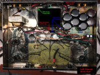
Helping out a friend with his Dynaco ST-70.
Can't get the hum outta the darn thing.
It was modified before he got it, then it came to me for help.
It had faulty wiring from the mods, which I removed and
redid. The caps were leaking on the SDS board, so those
were all replaced.
Moving Pwr tubes left to right,
Moving Pre amp tubes left to right,
Hum remains in the left channel.
Adding shorting plugs increases hum and it's not on BOTH channels.
Pulling only the left channel 7199 stops the hum.
So, I bought a new board and replaced it.
Somewhere, I read about that heater pin2 to pin2 should have continuity
and pin7 to pin7 should have continuity, but if pin2 to pin7 continuity
exists, this will cause hum. This amp has pin2 to pin7 continuity
everywhere in the amp without any tubes.
Still have hum in the left channel.
I couldn't find it with the scope.
Pic attached.
Tube replacements were also made.
Hum remains in the left channel.
Cheers,
Attachments
Last edited:
> has pin2 to pin7 continuity everywhere in the amp without any tubes.
Through the heater transformer.
And: "continuity" is for trailer-light mechanics. Electronics technicians have numbers. 2 Ohms, 20 Ohms?
Oh damn, you really have me laughing.
And yes, I guess it would be through the heater winding [SIC].
It's all good. You answered that, I've not answered yet.
So, to check I'll pull up the wiring from the board, then
take some not so trailer-light measurements from side to side
and from CT to sides.
Give me a few minutes to do this and I'll BRB to PRR.
since the pentode was dc coupled to the concertina splitters, i would dc lift the heater, and since that is only one channel, i suspect dc rail decoupling for that channel.....
if i remember it right, the filaments are earthed thru 0,1uf ceramic caps...or did you took them out?
if i remember it right, the filaments are earthed thru 0,1uf ceramic caps...or did you took them out?
Last edited:
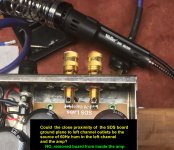
The hum channel is Heater Green, in OHMS
Close Socket (rear)
CT to p7 .029
CT to p2 .025
P2 to p7 .052
Far Socket (front)
CT to p7 .032
CT to p2 .036
P2 to p7 .075
Board sockets
CT to 5 .090
CT to 4 .042
5-4 .086
The non-hum channel Brn Heater, OHMs
close socket (rear)
CT to p2 .024
CT to p7 .026
P2 to p7 .061
Far socket (front)
CT to p2 .029
CT to p7 .029
P2 to p7 .068
Board sockets
CT to 15 .039
CT to 16 .042
15-16 .088
Nothing really stands out here.
since the pentode was dc coupled to the concertina splitters, i would dc lift the heater, and since that is only one channel, i suspect dc rail decoupling for that channel.....
if i remember it right, the filaments are earthed thru 0,1uf ceramic caps...or did you took them out?
I took them out and replaced with Panasonic films.
DC rail decoupling,
To DC lift the heaters?
By adding series resistance to each end?
Attachments
It looks to me like the choke is directly under one of the output transformers.
Steel Chassis . . . good luck.
On my original DYNA Stereo 70, the choke was mounted on a side wall, and Not mounted directly under one channel's output transformer.
Very Carefully . . . remove the choke from the amplifier, and use extension wires to the choke.
Try again and see what you get.
Question:
From the picture, it looks like the amplifier has been highly modified, including electrolytic caps mounted inside the chassis.
Modifications often end up with un-desired power supply ground loops, that get impressed onto the input and driver (concertina) tubes.
“Those who do not know history, do not know the meaning of Deja Vu”
Last edited:
6A3sUMMER,
Thanks. The choke is on the other channel.
However that would be simple enough to unscrew,
and move the choke outside the amp. it would end
up about 6 to 8 inches on the other side of the Hum channel.
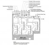
Yes, it has the SDS Capacitor board, came that way with
some leaky caps. I spent a good deal of time un-fornicating
the amp.
I'll replace the SDS board ground wire with a higher quality wire.
I've thought about relocating the CT wires from heaters and bias
tying them together and finding another location.
Thanks. The choke is on the other channel.
However that would be simple enough to unscrew,
and move the choke outside the amp. it would end
up about 6 to 8 inches on the other side of the Hum channel.
Yes, it has the SDS Capacitor board, came that way with
some leaky caps. I spent a good deal of time un-fornicating
the amp.
I'll replace the SDS board ground wire with a higher quality wire.
I've thought about relocating the CT wires from heaters and bias
tying them together and finding another location.
dc lifting heaters....by valve wizard.....The Valve Wizard
hum is different from splatters that goes away with dc lifting heaters....
hum is different from splatters that goes away with dc lifting heaters....
Thanks Tony,
That's a helpful link also.
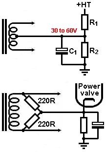
So, if I read this correctly,
instead of grounding the heater center taps,
(it has two one for the left channel, one for the right channel,
each drawing 3.450A current[3.0 + .450mA])
the amp would need two of the 30 to 60v
heater lifts, with each connected to +HT.
+HT would be the main b+ line.
There is one 30 to 60 volt feed for each center tap.
Thinking here.
Cheers,
I should say,
magandang umaga,
That's a helpful link also.
So, if I read this correctly,
instead of grounding the heater center taps,
(it has two one for the left channel, one for the right channel,
each drawing 3.450A current[3.0 + .450mA])
the amp would need two of the 30 to 60v
heater lifts, with each connected to +HT.
+HT would be the main b+ line.
There is one 30 to 60 volt feed for each center tap.
Thinking here.
Cheers,
I should say,
magandang umaga,
Last edited:
A point well taken as you are correct.You have spent more time trying to fix it then it would have taken to rebuild it.
I might as well see of the heater CT lift works, as long as I'm in here.
Before anything else.
Cheers,
At least I know now.
Taken with hand held Fluke 112, in excellent condition.
The heater lift came out to 48Vdc.
Resulted in and increase in static level hum 3mV
from 013mV to 016mV.
Chop sticking the input increased it to 033mV. Measured at the output jacks.
All the tube and related voltage were a bit high, but within expectations.
Standard B+ of 435Vdc is 460Vdc an increase of 5.7%.
Everything else followed suit.
el34
1,8 1.56Vdc
3 437 Vdc +6.6%
4 443 Vdc +6%
5,6 -35.15 Vdc 9.8%
7199 Vs are ak also.
So after taking these measurements,
with the meter to chassis grounded
looking for spurious VAC in the chassis...
B+ 464VDC 5.5VAC before filtering.
2nd cap section 442Vdc, .128Vac.
3rd cap section 374Vdc, .007Vac.
4th cap section 273Vdc, .007 Vac.
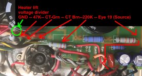
Heater CT Lift, Start of Lift;
273Vdc, .006Vac-->220K--48Vdc, .020Vac-->47K-->GND 0Vdc, .004Vac.
But didn't add extra filter cap because the cap board has a .1uf 630V panasonic
for each Heater CT. See post #6, C7, C8. Maybe I can link it here:?
https://www.diyaudio.com/forums/att...o-st-70-60-hz-hum-channel-st-70-sds-board-jpg
Or do I add another 10uf, 100uf, 220uf or larger at 100V or larger?
from local ground back to the middle of the series resisters and CTs?
If it's a heater CT, don't these love big caps? 2200uf or larger?
HERE IS THE INTERESTING (BUMMER) PART:
Hovering about 1 inch over various parts of the amp with pos meter lead.
(the negative meter lead still connected to ground.)
SDS Cap board .404Vac
Power Xfmr .356Vac
Choke .350Vac
Left EL34s; .424Vac, .433Vac
Left output Terminals .426Vac
Right EL34s: .339Vac, .340Vac
right output terminals .407Vac
Probably why the amp hums.
Maybe the Xfrmrs Shields are toast?
Cheers,
but feeling un-cheery.
Taken with hand held Fluke 112, in excellent condition.
The heater lift came out to 48Vdc.
Resulted in and increase in static level hum 3mV
from 013mV to 016mV.
Chop sticking the input increased it to 033mV. Measured at the output jacks.
All the tube and related voltage were a bit high, but within expectations.
Standard B+ of 435Vdc is 460Vdc an increase of 5.7%.
Everything else followed suit.
el34
1,8 1.56Vdc
3 437 Vdc +6.6%
4 443 Vdc +6%
5,6 -35.15 Vdc 9.8%
7199 Vs are ak also.
So after taking these measurements,
with the meter to chassis grounded
looking for spurious VAC in the chassis...
B+ 464VDC 5.5VAC before filtering.
2nd cap section 442Vdc, .128Vac.
3rd cap section 374Vdc, .007Vac.
4th cap section 273Vdc, .007 Vac.
Heater CT Lift, Start of Lift;
273Vdc, .006Vac-->220K--48Vdc, .020Vac-->47K-->GND 0Vdc, .004Vac.
But didn't add extra filter cap because the cap board has a .1uf 630V panasonic
for each Heater CT. See post #6, C7, C8. Maybe I can link it here:?
https://www.diyaudio.com/forums/att...o-st-70-60-hz-hum-channel-st-70-sds-board-jpg
Or do I add another 10uf, 100uf, 220uf or larger at 100V or larger?
from local ground back to the middle of the series resisters and CTs?
If it's a heater CT, don't these love big caps? 2200uf or larger?
HERE IS THE INTERESTING (BUMMER) PART:
Hovering about 1 inch over various parts of the amp with pos meter lead.
(the negative meter lead still connected to ground.)
SDS Cap board .404Vac
Power Xfmr .356Vac
Choke .350Vac
Left EL34s; .424Vac, .433Vac
Left output Terminals .426Vac
Right EL34s: .339Vac, .340Vac
right output terminals .407Vac
Probably why the amp hums.
Maybe the Xfrmrs Shields are toast?
Cheers,
but feeling un-cheery.
Attachments

Last edited:
Resulted in and increase in static level hum 3mVacWhat are you measuring ? Is it amp output connectors ?
from 013mVac to 016mVac.
Placing a chop stick inside the amp on the RCA center pole, to
the 470K ground resistor, increased the hum to 033mVac as
measured at the output jacks.
----------------
All the tube related voltages....
Were made at the applicable pin locations:
for example: el34 1,8 were made on the pin1,pin8 connection.
pos. lead to that location, negative lead on chassis ground.
It is the tip of the positive leave, that is inside the chassisWhen you say "howering over" is it you hand that is close to the parts in question ?
approx 1 inch away from the area stated, for example.
From the SDS Cap board the pos lead is held perpendicular to and approx
one-inch away from the SDS cab board, with my hand holding the the lead
at its end farthest from the measuring tip. The neg lead is connected to
chassis ground as with the tube socket number measurements.
As I've stated throughout the posts, a three prong power cord has beenIs the chassis connected to ground or is the chassis floating with no ground ?
installed, the GND connection soldered to the chassis, on the transformer
hold down screw. Please see the pic in post #1, green arrow call out.
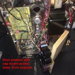
Here is how I installed the CT Heater Lifts.
Cap board close to outputs.
It didn't make a difference - hum still present.
Attachments
Last edited:
Another clue surfaced:
Measurments of Output Primary windings
taken with HP34401A, with tubes removed, unplugged:
Left
Blue pair = 40.020 Ohms
Wht-stripe = 48.560 Ohms
Right
blue pair = .114,63 KOhms or 114.63 Ohms
wht-stripe = 48.329 ohms
Any one have ST-70s outputs they don't mind measuring?
Cheers,
Measurments of Output Primary windings
taken with HP34401A, with tubes removed, unplugged:
Left
Blue pair = 40.020 Ohms
Wht-stripe = 48.560 Ohms
Right
blue pair = .114,63 KOhms or 114.63 Ohms
wht-stripe = 48.329 ohms
Any one have ST-70s outputs they don't mind measuring?
Cheers,
Those green wires are in the wrong place, too close to the driver board.
Those orange+white wires are in the wrong place, too close to the driver board.
Download the St70 manual from dynaco-doctor and look at the picture. Those wires are all bundled together 3" from the driver board.
Dynaco told people where to put every wire, and they meant it.
It looks as if the 5AR4 may be gone. If there are any silicon rectifiers, they need to have .01 or .1 uf 1000 v disc caps across them. Sharp edges of rectifier cutoff can cause 120 hz hum. If any diodes are fast recovery, ultrafast, or schottky, those produce RF interference worse than 1n4007. There is nothing sharp about the cutoff of a 5AR4 tube.
No, the left channel speaker jacks are low impedance connections, they won't pick up hum. The drivers, 7199 if you still have them, will. Notice dynaco put the input rca jacks as far as possible from the AC power parts, with as short a wire run as possible. If silicon rectifiers are used, 33 to 68 pf ceramic caps across the input jacks wouldn't hurt anything.
Last edited:
- Status
- This old topic is closed. If you want to reopen this topic, contact a moderator using the "Report Post" button.
- Home
- Amplifiers
- Tubes / Valves
- Dynaco ST-70 60 Hz Hum one channel