Actually just about anything will work! The more open loop gain you have there the lower the distortion should be but the distortion is quite low already.
You are absolutely correct!
")
Have you changed anything in the first stage?I use the ECC99 as first stage. A very fine tube.
I thought of trying 6CG7 in the first stage....

"theCarefulApproach"
I carefully studied this thread and decided to start my first design with tubes. In my brain work transistors, so please, be patient with me
I intend to build a headphone amp for loads from 32R - 600R. The idea with the WCF gave good results in the sim, and for the lower impedances, I decided to use an EDCOR WSM 600/150. High impedance devices will be connected directly...
Volume control will be done in the preamp. It's designed to accept 1Vrms as max input, with max. 3.8Vrms output @300R load.
I already have some 6N3P-EV and 6N6P-EV in my hands and plan to start with them.
Before I go into layout, fell free to give me any comments.
Attachments
I've chosen the transformer mainly to have it and to play with it. I never used transformers in audio circuits and this is a nice playground for all kind of new "experiences".
In the simulation, driving 32R was no problem... But the THD results were significantly better with the transformer for low impedance HPs; that's why I decided to be prepared... I'm pretty much aware that the sim is something different than the real circuit; but it will be interesting to see, where to find the main differences.
Btw, I corrected the CCS
Attachments
Last edited:
It´s working now.no I am under 5W/tube.
But now I am beginning to understand the importance of using matched tubes....
Or complicate the biasing etc for individual tube support (assuming a close curve for like models). Current, balance, etc all end up needing adjusting.
It depends how critical the application. For an ECC89 or 6N6P running at high heat like this into a heavy load like headphones, yes, you want the WCF to work in push-pull, which means you want to be able to adjust the WCF so that each half is delivering half the signal drive.
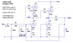
I was just playing with Koda's original 6N3P-version PCB circuit, thinking I might make a line stage out of it, to drive 10k ohms impedance loads.
Using a 250VDC B+, with a 6N3P as the totem-pole input tube and a 6922/6DJ8 as the CF-with-active-load output, and using four different models for each of the tubes (to deliberately unbalance them), I'm getting great looking results -- but only if the Rk of the top 6N3P triode (V1) is bypassed (or you use an LED to bias it).
Once this is done, and with 13dB NFB, the model predicts 0.02% THD at 1V rms into 10k ohms (1kHz). If I use identical models for the two each of 6N3P and 6922, I get 0.007% THD, which is too good to be true, for sure.
This totem-pole > CF w/ active load circuit looks noticeably better into 10k ohms than a standard common-cathode DC-coupled to cathode follower with resistor loads, and with similar level of NFB.
The operating points are:
6N3P
Vp = 125V (125.55V with the unbalance)
Vk = 2V
Ip = 4.3mA
Rk = green LED on top triode V1, 470R for bottom triode V2
6922/6DJ8
Vp = 125V
Vk = 3.2V
Ip = 8.25mA
Rk = 390R
The 6N3P is running at about 525mW plate dissipation.
The 6922 is running at about 1W plate dissipation (pretty hot, but not maxxed out).
The max Vp for 6DJ8 is 130V, so I think the above would be OK, as long as you don't mind running 6DJ8 tubes near their maximum ratings. I'd use 6N23P as the active-loaded CF if I needed to buy new tubes.
--
Last edited:
This is the circuit diagram (attached)
That's plate dissipation for each triode
--
The 6N3P is running at about 525mW plate dissipation.
The 6922 is running at about 1W plate dissipation (pretty hot, but not maxxed out).
That's plate dissipation for each triode
--
Attachments
Last edited:
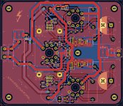
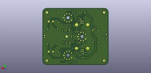
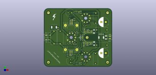
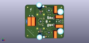
I finished the layout. Some minor changes were applied to the schematics, mainly for ground/return current control.
Let's see, what the board house will deliver
Let's see, what the board house will deliver
Attachments
to keep you updated...
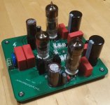
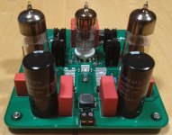
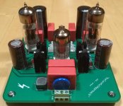
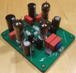
components soldered, first trying on... everything as expected so far. I did not apply any voltage as I need to build a test fixture first. That's something for the weekend
components soldered, first trying on... everything as expected so far. I did not apply any voltage as I need to build a test fixture first. That's something for the weekend
Attachments
- Home
- Amplifiers
- Tubes / Valves
- 6N3/6N6 headphone amp using PCB.