I'm seeing some behavior that I don't understand, and I'm hoping someone can explain it to me.
I'm using an 815 tube (dual beam tetrode with shared screens and cathodes) in class AB1. The data sheet specifies a maximum grid resistance of 15K per side. That's all well and good.
Plate voltage is 500V, idle current is 37mA per side. Screen voltage is 190, dissipating ~1.5 mA total at idle.
I've got 10K grid stoppers, and I'm experimenting with a dual-ganged pot in place of grid leaks, to better understand the behavior at different values. From 0-5K ohms on the pot (10-15K total grid resistance), screen current stays steady. But when I go beyond that, it climbs quickly; by 25K total grid resistance, the screens are dissipating 9mA, and by 40K they're at the 32mA max spec.
I get that I'm abusing the specs. But what I don't get is why screen current would increase with higher grid resistance. Higher grid resistance shifts the bias down, which if anything should reduce screen current, not increase it.
Could it be caused by the big disparity between plate and screen voltage? The tube has a 225V limit on the screens, and I'm at 190 because that was a really convenient voltage to regulate with a simple series pass regulator with VR tubes for reference.
What am I misunderstanding?
Last edited:
First make sure the 815 isn't oscillating, scope the OP.
I would guess with a higher Rg any charge current on the grid can't leak to ground, are you monitoring the Vg when you adjust the pot? If there's a charge on the control grid electrons from the cathode will flow more causing Ig2 to go up,though one would think the anode would pull electrons past the screen grid having a high potential.
Again,check for parasitic oscillation,it's the cause of most of the weird sh*t one encounters.
Andy.
Are you sure about that? Check your textbooks!Higher grid resistance shifts the bias down,
")
There are two forces at work on the grid, and they work in opposite directions.
Take an "ideal" vacuum tube and fire up its heater. Electrons will be pushed out of the cathode into the surrounding vacuum by the heat in the cathode. Without any external voltages in the tube influencing their movement they will "cloud" around the cathode, but some will randomly strike the grid and a few will land there. With no external path for current to flow, the grid will accumulate a negative charge. This charge will continue to build on the grid, and in a high quality tube go negative enough to cut the tube completely off even if there was a positive voltage on the tube's plate.
Take a really sensitive high impedance volt meter, and connect it between the cathode and the control grid. The voltmeter would read a negative voltage, but at the same time, provide a path to bleed off this negative charge due to it's internal resistance. In a large TV sweep tube with a huge hot cathode, the random collection of electrons hitting the grid can push the grid a few volts negative even with a cheap digital meter connected from grid to cathode. The resistance in the meter "leaks" electrons off of the grid, reducing the negative voltage. This is the basis for "grid leak bias" seen in old amplifiers and radios preceding 1940. The cathode of the tube was grounded and a high value (1 to 10 meg) resistor was used from grid to ground to develop bias.
No tube is "ideal," all have an imperfect vacuum and internal impurities. These tend to get worse with time and use, as some of the impurities trapped in the internal elements get released into the vacuum.
These impurities are collectively referred to as "gas." At low pressure (the near vacuum) this gas will ionize creating the blue to pink glow often seen around the electrodes inside the plate of a tube that is operating under high power. This is unwanted, and not the same thing as the harmless blue glow on the glass itself. The glow is created by atoms losing an electron, and then getting it back. This tends to give the ionized gas cloud a positive charge capable of readily stealing electrons off of a grid wire, thus making the grid more positive.
In a small signal tube the negative collection of electrons on the grid tends to be the dominant force, but this will eventually give way to gas if the tube is used long enough.
In a high powered tube, especially a modern new production tube assembled under less than ideal conditions, there will be a balancing act, with the electron cloud putting more electrons on the grid, than ions stealing them. Beat that Russian KT88 at 85% of maximum dissipation until it's getter is nearly gone, and the tides have turned.
There is a minimum grid circuit resistance spec to give those two opposing forces a path to the cathode regardless of which one is winning the battle. There will be a point there the ions start upsetting the grid voltage which causes the tube current to increase. It will get worse as the tube gets hotter, and eventually lead to a red plate runaway. Usually the distortion gets noticeable before this happens, but runaway occurs if this is ignored. The larger the grid resistor is, the more likely it is to happen. That's why I tend to use a mosfet driver on the grid pin and a fat low valued resistor from the grid directly to the negative voltage supply.
In addition, here is an interesting article on the grid current. How many heard of "grid current loadline"? Maybe not all. For proper grid current in tube, it must be outside of grid current loadline of grid characteristic curve as increase grid resistor value will cut into loadline which is not good because it makes grid more positive.
Grid Current and Grid Blocking
Grid Current and Grid Blocking
Attachments
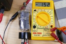
Here is a simple test. I took a good 26LW6 tube from my UNSET amp, connected the heater to a power supply set at 26 volts.
I connected a $4 meter from cathode to G1. The meter reads about 1.5 volts.
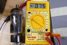
I swap the tube for a well worn and slightly gassy tube, and the meter reads 750 mV.
I connected a $4 meter from cathode to G1. The meter reads about 1.5 volts.
I swap the tube for a well worn and slightly gassy tube, and the meter reads 750 mV.
Attachments
Interesting post George
Andy.
Does that mean that Rg1 is too big and needs reducing?These impurities are collectively referred to as "gas." At low pressure (the near vacuum) this gas will ionize creating the blue to pink glow often seen around the electrodes inside the plate of a tube that is operating under high power. This is unwanted, and not the same thing as the harmless blue glow on the glass itself. The glow is created by atoms losing an electron, and then getting it back. This tends to give the ionized gas cloud a positive charge capable of readily stealing electrons off of a grid wire, thus making the grid more positive.
Andy.
Generally speaking you are safe if you do not exceed the maximum grid circuit resistance given in the data sheet. This is the combined total resistance from the G1 pin on the tube to the cathode, ground, or other stiff negative voltage source. If you are running two tubes in parallel, the resistance must be half the published value unless separate bias circuits for each tube are used.
Many modern new production tubes blindly copy the old data sheets for the tubes that they make, which may not even resemble the tubes that they "copied." How many new production 6V6 types have the oval plate structure seen in the originals? The published data sheets for these tubes do not really apply, but many of them have a reputation for robustness even well beyond the published 315 volt plate rating. That's not the case with some batches of expensive Russian 6550's though.
It would be wise to keep an eye on the bias current often whenever a new amp build is put into service, and at regular intervals after that. Usually the bias current in a tube declines over time as the cathode emission drops off. If the current creeps upward over time, the tube may be gassy, or the G1 circuit resistance is too high. Either way if this is left unchecked a runaway event may happen if the gassiness increases faster than the emission drops off. Often a diminishing getter spot will accompany the increasing gassiness, but this is not always the case.
Another concern is the act of replacing powertubes with something else ,
one example is to replace EL34 with KT77.
EL34 allows up to 700k grid grid resistor while KT77 is limited to 250k
A KT77 in this position might not redplate at once but one should not be
surpriced if the risk of redplating is greatly increased.
One should never take such advices ad notam but always check data and / or
check with the amp's documentation before installing unsuitable tubes.
The above is lot limited to EL34 replacement but to all power tubes.
The bottom line: never trust what is told on Internet ( including this post) without
checking facts.
That only applies when you use the parasitic GK diode to develop the bias, and that's never done for audio amplification. You haven't specified how you're developing the bias. Need to know that. Being that the 815 is a VHF type, it's highly likely it was never designed with the usual audio bias -- fixed, cathode, or a combination of cathode and fixed bias -- in mind..
I get that I'm abusing the specs. But what I don't get is why screen current would increase with higher grid resistance. Higher grid resistance shifts the bias down, which if anything should reduce screen current, not increase it.
No: your screen voltage is within spec. Running it a bit low costs some plate current, but at the same time helps prevent screen poofage. How's your plate current? Is it steady or does it creep? I had some gassy 6BQ6GTB's where the plate current would not settle down. Even though there was no visible glow, they were still gassy enough to cause that plate current creep. If that's the case, then chuck it. If that's not the case, then keep the gtid resistance within spec. 15K seems awfully low, but you'll just have to live with it. Include a stiff driver that can operate into that load: cathode follower or source follower.Could it be caused by the big disparity between plate and screen voltage? The tube has a 225V limit on the screens, and I'm at 190 because that was a really convenient voltage to regulate with a simple series pass regulator with VR tubes for reference.
What am I misunderstanding?
If you have another 815 tube, try it and see if it behaves the same. For those who have never met this two headed alien tube it is a pair of 2E26 tubes in the same fat octal envelope. The 2E26 is a "baby" 6146.
All were used in audio amp duty, albeit for AM modulator use. All three tubes are also rated for AB2 use where a single 815 or a pair of 2E26's can make 54 watts of audio.
All were used in audio amp duty, albeit for AM modulator use. All three tubes are also rated for AB2 use where a single 815 or a pair of 2E26's can make 54 watts of audio.
Thanks for all the ideas and thoughts. It was oscillating. I had oscillation problems on the breadboard, ultimately traced to using the same power supply node to feed both the phase inverter and a direct-coupled CF that was swinging 200Vpp. I resolved that, but as I've built it into the chassis, I guess I've introduced new opportunities for coupling.
Given that it's only a problem at settings that would be shoving 25W into a 102 dB speaker, I'm not going to spend any more time chasing it.
Given that it's only a problem at settings that would be shoving 25W into a 102 dB speaker, I'm not going to spend any more time chasing it.
There are two forces at work on the grid, and they work in opposite directions. ...
This is a really interesting, thanks for all the insight. One question, regarding your last comment - are you saying that you apply bias directly to the grid, rather than on the "upstream" side of the mosfet driver?
No, the bias voltage is applied to the gate of a mosfet source follower, or the grid of a tube cathode follower, the source or cathode directly drives the grid with a suitable low value resistor from the grid to a negative voltage supply.
Some info is here:
Power Drive | Tubelab
Cookbook | Tubelab
Some info is here:
Power Drive | Tubelab
Cookbook | Tubelab
That only applies when you use the parasitic GK diode to develop the bias, and that's never done for audio amplification. You haven't specified how you're developing the bias. Need to know that. Being that the 815 is a VHF type, it's highly likely it was never designed with the usual audio bias -- fixed, cathode, or a combination of cathode and fixed bias -- in mind.
I'm using fixed bias from a regulated supply. (Heeding all that advice about "if either screen or bias is regulated, the other must be also".) The datasheet allows for grid leak, fixed, cathode, or mixed.
No: your screen voltage is within spec. Running it a bit low costs some plate current, but at the same time helps prevent screen poofage. How's your plate current? Is it steady or does it creep? I had some gassy 6BQ6GTB's where the plate current would not settle down. Even though there was no visible glow, they were still gassy enough to cause that plate current creep. If that's the case, then chuck it. If that's not the case, then keep the gtid resistance within spec. 15K seems awfully low, but you'll just have to live with it. Include a stiff driver that can operate into that load: cathode follower or source follower.
Plate current is nice and steady, at least over the 2 hour burn-in test that I've done. Yeah, 15K is ridiculously low. I'm just driving it with a 6J6 PI, which can easily drive it to clipping (and then some). I'm staying in AB1 on this one; in a future build, I might experiment with pushing into AB2.
- Status
- This old topic is closed. If you want to reopen this topic, contact a moderator using the "Report Post" button.
- Home
- Amplifiers
- Tubes / Valves
- Larger grid leak causing increased screen current?