Hello to all reading this,
I would like some guidance on the design decisions that follow in my 6l6 amplifier build:
Two years ago I decided that I would like to build two Monoblock 6l6 based amplifiers. At the time (with a certain budget restrain) I ordered components that would allow me to build "Williamson" Ultra Linear style amplifiers with bias points slightly adjusted for a somewhat lower supply voltage. I completed two chassis, each with a power supply transformer, OPT and 5 tube sockets installed.
Then came the quite naïve realization (after carefully reading many articles on the Williamson amplifier) that my choice of output transformer might become a severe design limitation. At the time (again due to budget limitations) I chose the Hammond 1620 output transformer. My reasoning was that the 20 Watt power limitation was not going to be too big of a deal as my B+ supply voltage was going to be somewhat lower anyway (and thus the resulting output power).
After reading up on the specifications required for a Williamson output transformer I concluded that the frequency bandwidth of the Hammond transformer (30Hz --> 30Khz -1db) and leakage inductance might become a severe issue.
Also the inductance of the primary winding was unknown, so I decided to contact Hammond in order to get some numbers on the primary inductance in Henry after the realization that the output transformer needs to be one of a certain high quality in order to stabilize the Williamson design. Williamson stated in his article that the primary inductance must be no less than 100H in order to function well and Hammond confirmed that the 1620 could achieve an 106.5H inductance (under certain conditions of course).
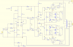
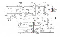
I started looking all over the Internet to find people that have pulled off a Williamson build with somewhat inferior OPT's. I found one instance where somebody used the Hammond 1620 in a successful build by reducing feedback and some other (somewhat peculiar) design choices [img1]. It strikes me the the first half of the input 6SN7 seems to be starved and the concertina anode/cathode resistors seem to be quite low in resistance and thus allows for a higher current. Another "unique" aspect seems to be the grid stopper resistors on the 6SN7 drivers and 10k grid stoppers on the KT66. The rather high bypass 1nf capacitor across the feedback network also strikes me as odd (any comments?).
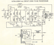
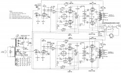
The second design I found was not a Williamson type per-se but a design by Acrosound using (correct me if I am wrong) a floating Paraphase type design [img2]
My questions then would be:
* 1: who can say (from experience or knowledge) which of these two circuit designs (Williamson or Acrosound) has the highest chance of being stable with the given OPT?
* 2: Can somebody with more experience comment on the design [img1] and what the key aspect is that makes it work and keeps the phase shift in check with the Hammond 1620. Also can we improve upon the design (to simplify it somewhat again)?
Thanks in advance,
Pim
I would like some guidance on the design decisions that follow in my 6l6 amplifier build:
Two years ago I decided that I would like to build two Monoblock 6l6 based amplifiers. At the time (with a certain budget restrain) I ordered components that would allow me to build "Williamson" Ultra Linear style amplifiers with bias points slightly adjusted for a somewhat lower supply voltage. I completed two chassis, each with a power supply transformer, OPT and 5 tube sockets installed.
Then came the quite naïve realization (after carefully reading many articles on the Williamson amplifier) that my choice of output transformer might become a severe design limitation. At the time (again due to budget limitations) I chose the Hammond 1620 output transformer. My reasoning was that the 20 Watt power limitation was not going to be too big of a deal as my B+ supply voltage was going to be somewhat lower anyway (and thus the resulting output power).
After reading up on the specifications required for a Williamson output transformer I concluded that the frequency bandwidth of the Hammond transformer (30Hz --> 30Khz -1db) and leakage inductance might become a severe issue.
Also the inductance of the primary winding was unknown, so I decided to contact Hammond in order to get some numbers on the primary inductance in Henry after the realization that the output transformer needs to be one of a certain high quality in order to stabilize the Williamson design. Williamson stated in his article that the primary inductance must be no less than 100H in order to function well and Hammond confirmed that the 1620 could achieve an 106.5H inductance (under certain conditions of course).
I started looking all over the Internet to find people that have pulled off a Williamson build with somewhat inferior OPT's. I found one instance where somebody used the Hammond 1620 in a successful build by reducing feedback and some other (somewhat peculiar) design choices [img1]. It strikes me the the first half of the input 6SN7 seems to be starved and the concertina anode/cathode resistors seem to be quite low in resistance and thus allows for a higher current. Another "unique" aspect seems to be the grid stopper resistors on the 6SN7 drivers and 10k grid stoppers on the KT66. The rather high bypass 1nf capacitor across the feedback network also strikes me as odd (any comments?).
The second design I found was not a Williamson type per-se but a design by Acrosound using (correct me if I am wrong) a floating Paraphase type design [img2]
My questions then would be:
* 1: who can say (from experience or knowledge) which of these two circuit designs (Williamson or Acrosound) has the highest chance of being stable with the given OPT?
* 2: Can somebody with more experience comment on the design [img1] and what the key aspect is that makes it work and keeps the phase shift in check with the Hammond 1620. Also can we improve upon the design (to simplify it somewhat again)?
Thanks in advance,
Pim
Attachments
No experience with Hammond transformers, nor with this specific implementation of the Williamson amp.
Also, I'm more of a tweaker than an theoretician. Sorry.
However, I did build a few amps similar to these two over the years.
I have read about instability in the Williamson, but haven't had that problem myself.
Maybe because I keep the GNFB low. For high levels of GNFB, the OPT needs to be of very high quality.
The feedback bypass cap depends on circuit design and characteristics of the OPT. So, either stick to a known design, using that specific OPT, or determine it empirically: hook up load resistors and a o-scope, feed it a square wave and try different cap values to find the one that gives the best wave (reduces/eliminates overshoot and ringing without rounding off the square).
One question you should ask yourself: how much power (and damping) do you really need?
The 1620 OPT is not the biggest transformer, EI-78 if I'm not mistaken.
The trusty old PP EL84 amp next to me here uses EI-84 sized OPTs.
UL 6L6 might be a bit much for what those 1620's can handle. Triode mode would be my choice here, or 6V6's. Triode mode already reduces distortion and output impedance, so you could get away with a little less GNFB.
The long design thread 6L6GC AB2 Amp ultimately lead to a 6SN7 LTP into another 6SN7 LTP.
It gives the proper amount of gain for PP 6L6.
It gives the proper amount of gain for PP 6L6.
Parafeed813 is right about starting the design process by deciding what parameters you actually need.
1) What speakers will you be using with this amp? The more sensitive the speaker, the less output power will be required from the amplifier. The smoother the speaker's impedance curve, the less damping will be required of the amplifier.
2) How big is your listening room? The larger the room, the more power output you will need from the amplifier. The smaller the room, the less power needed.
3) Related - How far away from the speakers do you sit when you listen to your system? The farther away, the more power you will need to achieve a certain playback sound pressure level (SPL) at the listening position. The closer you are to the speakers, the louder they will sound to you, so the less output power you would need from the amplifier.
If you don't need gobs of power, you may be happy with triode-wiring your 6L6s. You will probably get about 10 watts per channel that way.
Triode wired 6L6s will run cleaner than in pentode, so you may be able to get away with less negative feedback around the amplifier.
Triode mode = more damping over the loudspeaker than pentode. That's another reason why you should be able to get away with less NFB if you go with triode mode.
Less NFB = less problems with stability, therefore less need for an OPT with super-low leakage inductance, etc.
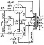
Have you ever seen the "Albert Einstein" amplifier? That's an amplifier someone supposedly made for Albert Einstein, based on the Williamson design but using 6B4G directly-heated triodes as the output tubes. That would give you an idea of what might be possible with what you have.
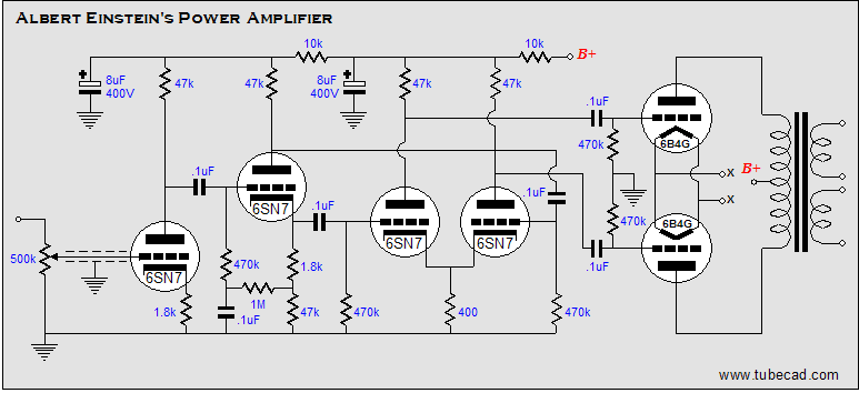
As you can see, it's basically a Williamson, with a slightly different cathodyne/concertina phase splitter. It also employs no global NFB loop.
Whether an amp something like that would work for you completely depends on what kind of speakers you use and the size of your listening space. But maybe?
--
1) What speakers will you be using with this amp? The more sensitive the speaker, the less output power will be required from the amplifier. The smoother the speaker's impedance curve, the less damping will be required of the amplifier.
2) How big is your listening room? The larger the room, the more power output you will need from the amplifier. The smaller the room, the less power needed.
3) Related - How far away from the speakers do you sit when you listen to your system? The farther away, the more power you will need to achieve a certain playback sound pressure level (SPL) at the listening position. The closer you are to the speakers, the louder they will sound to you, so the less output power you would need from the amplifier.
If you don't need gobs of power, you may be happy with triode-wiring your 6L6s. You will probably get about 10 watts per channel that way.
Triode wired 6L6s will run cleaner than in pentode, so you may be able to get away with less negative feedback around the amplifier.
Triode mode = more damping over the loudspeaker than pentode. That's another reason why you should be able to get away with less NFB if you go with triode mode.
Less NFB = less problems with stability, therefore less need for an OPT with super-low leakage inductance, etc.
Have you ever seen the "Albert Einstein" amplifier? That's an amplifier someone supposedly made for Albert Einstein, based on the Williamson design but using 6B4G directly-heated triodes as the output tubes. That would give you an idea of what might be possible with what you have.
As you can see, it's basically a Williamson, with a slightly different cathodyne/concertina phase splitter. It also employs no global NFB loop.
Whether an amp something like that would work for you completely depends on what kind of speakers you use and the size of your listening space. But maybe?
--
Last edited:
I measured a Hammond 1620 a few years ago, primary was 230 Henries at 10V, 20 Hz. Leakage inductance was 8.6 mH at 4ohms (secondaries in parallel), 20 mH at 8. The new ones with 4-8-16 taps may not be as good, but will let you use the 16 Ohm tap for feedback, which was not a choice with the early one unless you wired for 16 Ohm speaker. Below is impedance (Z & theta) vs. frequency, with 4 and 8 Ohm terminations. I suspect the new ones would do well at 16 Ohms, worse at 8, even worse at 4
Attachments
Last edited:
Einstein's amplifier would make an excellent phase-shift oscillator if you applied any feedback... even unintentional feedback if the power supply impedance is high. There are three identical R-C coupling networks cascaded. At some low frequency, each will have a 60 degree phase shift - voila - 180 degrees! There's a reason the Mullard circuit has been used so widely - one less R-C network than the Williamson.
You have a 6.6 kOhm Raa 43% UL output transformer and 6L6GC output tubes.
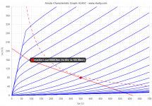
With 350V across the tube and 80 mA bias you will be at 28W dissipation (close to the 30W) at idle and you will hit the g1=0 at around 160mA with plates around 85V, still in class A1, reaching exactly 20 Wrms.
Has anyone ever used 6L6GC in those conditions?
With 350V across the tube and 80 mA bias you will be at 28W dissipation (close to the 30W) at idle and you will hit the g1=0 at around 160mA with plates around 85V, still in class A1, reaching exactly 20 Wrms.
Has anyone ever used 6L6GC in those conditions?
Attachments
@Tom Bavis: Those measurements on the Hammond 1620 are very useful, I indeed have the older version of the transformer (not the A one). I have been thinking about the Mullard circuit as I have 2 red can 6SJ7 tubes laying around. The only problem is that I do not know the state of the tubes and I do not have a tube tester at hand.
@zintolo: I will be using the 6L6 (old version) in this circuit with a max dissipation of 19Watt (some 380 volts @ 50ma).
I will be honest in that I find it hard to pick a topology for this amplifier. The Mullard will be the most stable, The H&F circuit is nice but may give too much gain, The Williamson might become unstable with the given transformer.
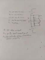
pwgtang,
There is no DC forward bias on those transistors.
(no resistor from the collector to the base).
The only possible conduction of those transistors is caused by:
The charging current of C1.
The leakage current of C1.
Not a good idea.
During power up, C1 capacitance has to charge up, the transistor will conduct Lots of current.
After C1 charges, of C1 does not have any leakage current, the transistors will not conduct.
But the cathodes will go to a high voltage, is that high enough to cause the transistor to go into overvoltage breakdown?
Or, perhaps the schematic had the collectors and emitters reversed.
Be careful, the base and collector are not interchangeable, unless the reverse voltage between the emitter and base will never exceed the base emitter reverse voltage specification, typically it is 5 to 7V (depands on the transistor).
If you reverse the transistor collector and emitter, you first have to change from NPN to PNP.
The circuit does need to be modified in order to provide proper operation.
“Those who do not know history, do not know the meaning of Deja Vu”
Last edited:
The transistor is supposed to be off at idle. It only turns on when the tube leaves class A. Discussion of the circuit is found here:
300w-5-bias-stabilizer
300w-5-bias-stabilizer
The Williamson circuit has 3 gain stages inside the feedback loop, which spells TROUBLE!!! To my knowledge, very few brave souls dare to produce and market it: only Heathkit comes to mind. And the schematic in img1 has way too many unnecessary and/or weird stuff to make it even worth discussing: C15, R37, C1/R6, C2R7, and all the bias stuff at the output.
The Acrosound circuit, also known as the Mullard circuit, is much better and widely used by Conrad-Johnson, VTL and so on, not to mention virtually all the guitar amps. The Acro design is kind of dated; try to search for schematics of the more contemporary stuff I mentioned.
In any case, go for the best output transformer you can find and afford. Hammond are just OK, there're better stuff from Sowter (UK), Lundahl (SE), Hashimoto Sansui (JP), etc., and one of your fellow country man Vanderveen has been pushing toroidal OPT for some time, but I have no first hand experience with these.
Last edited:
Thanks for the replies,
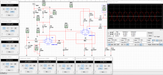
I took inspiration from the Mullard design as some have pointed out that would be the most stable design. I substituted the Pentode input stage with a self biased direct coupled Cascode stage, the first simulation look fine [img1] and the gain is about 250x. I plan to couple these stages to an ultra linear output stage like seen in [img2].
The gain obtained from the input stage + phase splitter + output stage should provide enough gain for ample feedback. There is only one CR couple network between the phase splitter and the output stage and should reduce phase ship enough for stability (correct me if I am wrong).
Any opinions on the design") ?
?
Thanks,
Pim
I took inspiration from the Mullard design as some have pointed out that would be the most stable design. I substituted the Pentode input stage with a self biased direct coupled Cascode stage, the first simulation look fine [img1] and the gain is about 250x. I plan to couple these stages to an ultra linear output stage like seen in [img2].
The gain obtained from the input stage + phase splitter + output stage should provide enough gain for ample feedback. There is only one CR couple network between the phase splitter and the output stage and should reduce phase ship enough for stability (correct me if I am wrong).
Any opinions on the design
?Thanks,
Pim
Attachments
Hammond 1620 has 210H primary? Wow, that's a very high number. Are we sure that's accurate?
Re: Williamson topology and 'Einstein' amplifier --
1) The idea would be to use the 6L6s as triodes for the outputs, so less need for gobs of NFB.
2) Don't use as much NFB as in the original Williamson design and also change parts values to stagger the pole points so that the time constants are at different frequencies, far enough away from each other that they do not create 180 degree phase shifts at low frequencies.
The Mullard circuit is more stable but at the expense of linearity, which means you'll be more likely to need to apply NFB. Not that that is a bad thing. Just something to consider.
Also re: Mullard circuit -- You'll probably want to use a triode as the input voltage amplifier, not a pentode. The original design had too much gain for today's signal sources, so would be too sensitive and noisy (it was designed back in the day when a tape head or tuner might only make 200mV peak output, as opposed to today's 2V RMS @ 0dBFS).
It is hard to pick a topology. Everything is a compromise between this and that.
I think the best topology for a push-pull tube amplifier is the one described in the push-pull Class AB2 6L6GC amplifier thread. Its only downside is that it needs a separate negative voltage supply and a constant current sink to feed the tail of the LTP phase splitter (and perhaps the second differential amplifier). An examples is attached. It's only meant to show the topology, not an example of a finished design for your application.
Attachments
Last edited:
Thanks for the replies,
I took inspiration from the Mullard design as some have pointed out that would be the most stable design. I substituted the Pentode input stage with a self biased direct coupled Cascode stage, the first simulation look fine [img1] and the gain is about 250x. I plan to couple these stages to an ultra linear output stage like seen in [img2].
Ultralinear output is a good compromise between triode- and pentode-like characteristics.
- You get get more power than triode, but less than pure pentode.
- You get lower THD than from a pentode output stage, but more than from triode.
- You get better intrinsic damping than from a pentode stage, but worse than from triode.
Because of the above, you will absolutely need to employ NFB of some kind around a UL output stage. But you won't need as much NFB for acceptable damping/THD as you would if you used a pentode output stage.
If you want to include the OPT in the NFB loop, you'll need to consider its resonances and reactances. Those will place a hard limit on how much NFB you can employ before you see instability. The quality of the OPT will define what you can do.
If you consider a 'Schade' feedback scheme (local feedback from output tubes' plates to their grids) then you can leave the OPT out of the NFB loop, or use much less global NFB (employ nested feedback loops like was done in the harman-kardon Citation II amplifier).
Everything is a compromise between this and that.
The gain obtained from the input stage + phase splitter + output stage should provide enough gain for ample feedback. There is only one CR couple network between the phase splitter and the output stage and should reduce phase ship enough for stability (correct me if I am wrong).
How much NFB is 'ample'? 10dB? Are you going for the outer limits, like 20dB?
Yes, having only one RC coupling between input and output tubes does help a lot. Of course you still have the OPT in the global NFB loop...
There's a lot to think about. Isn't this fun?
--
Last edited:
...
I took inspiration from the Mullard design...
I mentioned Mullard for historical reasons only.
I wouldn't be too dogmatic about the circuit: during the 3/4 century or so since its publication, there's been some improvements, not a lot, but still, why reinvent the wheel?
As an example, take a look at the Conrad-Johnson MV75, a very good amp in its own right:
What I'd do:
- Remove the unnecessary output bias Leds
- Use big caps + bypass for the power supply
- Use Schottky diodes
- Use snubber/EMI filter for the power transformer
- (Optional) Assuming you'll roll your own, make sure you have a bias supply with enough beef, maybe 10-20mA more than usual, and make an extra negative supply for the longtail pair, replacing the 10K tail resistor with some higher value one (some arithmetic required). I think that's the main reason for the alleged lack of linearity of the Mullard circuit: the usually smallish value of the tail resistor keeps the inverter from acting as a true differential amplifier, hence the 500K pot to compensate.
- Since you can sim, do a full circuit analysis with the idle current of the longtail pair as a parameter: the Jadis amps use a 12AX7 there, running at a current that's way too low.
Last edited:
I wouldn't be too dogmatic about the circuit:
+1
Another 'Mullard-inspired' design was the harman-kardon Citation II. Its roots in the Mullard are obscured by its use of pentodes, nested feedback loops and other details, but at its base it's a common cathode voltage amplifier coupled to a long-tailed pair driving the push-pull output pair.
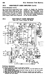
On the other hand, many folks on this forum have extolled the virtues of the RCA 50-Watt High-Fidelity Amplifier from the RCA Tube Manual. That's a Williamson topology using pentodes with nested feedback loops and other details added.
Implementation is crucial.
--
Attachments
6550 tubes . . . some are not as strong as some other 6550 tubes.
Some are Robust; Some are Busted.
The maximum Rg1 Resistance (to Cathode potential) specification when using Fixed Adjustable Bias is 50k Ohms.
Post # 18 and Post # 19 are both breaking the rules for 6550 tubes.
Change the circuit values, or use KT88 tubes (better Rg1 specification).
And lowering Rg1 to 50k makes the driver tubes have to work harder, and to distort more.
Use any 100k Rg1 resistor, and any 6550, and see how long it works . . .
5 years, or 5 minutes after the tube warms up.
Your Mileage May Vary (YMMV).
Darn those silly tube specifications !
“Those who do not know history, do not know the meaning of Deja Vu”
- Status
- This old topic is closed. If you want to reopen this topic, contact a moderator using the "Report Post" button.
- Home
- Amplifiers
- Tubes / Valves
- Asking for guidance on 6L6 PP build/design selection