Hi Jona,
do I get you right that both output transformers are from the same unit that also had the EL84's? Then I'd re-use them in a PP amplifier with a pair of EL84's and a 12AX7, either as a voltage amplifier + Concertine phase splitter, or, what I'd prefer, a Schmitt/LTP PI. Apply sufficient NFB.
No need to buy other tubes, unless yours' are worn out.
And measure your OT's again with applying 6.22 Vac (or so) to the secondary. The result might be somewhat different - and more reliable.
Best regards!
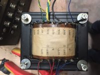
I remeasured the OPT backwards at the 8 ohm output, as suggested and the calculated impedance is 7.192k --> ((188/6.27)^2)*8
I'd indeed like to reuse as much as possible from the tubes and transformers. as those seems to be the most expensive components. All passive's I will replace as they tend to drift a lot over the years, and caps will probably have dried out. Btw: the amp was definitely not working when I got it (burned up resistor right before the output, so a non functional Tube is a possibility

I see a lot of designs passing, but since I'm still reading up on VTA designs it is getting difficult to differentiate between them. Therefore I'll make a clear listing of the items I intend to use. At this point I don't think I'm in for the best possible amp with these components, just something that works with the items I have.
Later on, if I have a better understanding of these amp's I might rebuild it or build another one. I thought of getting a ST-35 kit, but they seem very difficult to procure in Belgium/Europe.
So here is the list of components I have and hope to use:
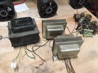
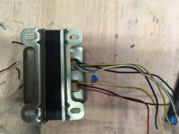
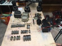
Power transformer (Pri: 2x117V; Sec: 6.3V@3.1A, 6V@2.1A, 6.3V@2.2A and 260V@410mA with center-tab)(picture included)
OPT(7.2K Pri: center tab, no tabs for UL; Sec: tabs for 4, 8, 16 and 32 Ohm)
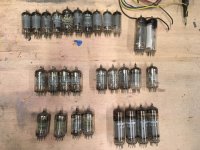
Tubes: 4 EL84 tubes and plenty of 12AU7, 12AX7 or 12AT7 to choose from
I have no rectifier tube, so preferably silicon diodes
I'm willing to do some recalculations if needed, but need a proper design to start from that fits those components, and maybe some pointers to what wil need to be recalculated
Attachments
I continue to recommend PP EL34 in triode with no global feedback with what you have, since the mains transformer is marked 410mA. It won't do any harm to get a new quad of output tubes. The Russian 6P3S are cheap enough from e.g. Ukraine. They are a 6L6 or 5881 substitute, similar to EL34 but look closely at the pinout of the socket depending on which of these you use. The EL34 has an extra connection to pin 1. You should specify a matched quad.
4 pcs. NEW TESTED 6P3S (analog 6L6 / 6L6GT / 6L6GC ) USSR TUBES | eBay
That's just my opinion and what I'd build myself. An all triode amp is a better sound to my ears.
4 pcs. NEW TESTED 6P3S (analog 6L6 / 6L6GT / 6L6GC ) USSR TUBES | eBay
That's just my opinion and what I'd build myself. An all triode amp is a better sound to my ears.
One exemple with 6P14P-EV which i was build. i was using paraphase for phase splitter and the sound is amazing
DANO-Lab - Paraphase Push Pull Amplifier
6P14P-EV (EL84) &... | Facebook
DANO-Lab - Paraphase Push Pull Amplifier
6P14P-EV (EL84) &... | Facebook
Anode feedback puts stress on the driver circuit giving complications. While a first build could be so easyIt depends.
GFB is not needed to reduce the output impedance, Scade feedback works well.
Pentode without any feedback is typically a current amp.
Any high output impedance amplifier wants to see a very flay speaker impedance curve (rare, bu tthey exist) or with an impedance curve that the convolution of part of the speaker impedance with the FR (measured with a voltage amp) tends to equalize/extend the FR. Some speakers (like the Fostex FExx6 series) what to see a high output impedance amplifier.
I continue to recommend PP EL34 in triode with no global feedback with what you have, since the mains transformer is marked 410mA. It won't do any harm to get a new quad of output tubes. The Russian 6P3S are cheap enough from e.g. Ukraine. They are a 6L6 or 5881 substitute, similar to EL34 but look closely at the pinout of the socket depending on which of these you use. The EL34 has an extra connection to pin 1. You should specify a matched quad.
4 pcs. NEW TESTED 6P3S (analog 6L6 / 6L6GT / 6L6GC ) USSR TUBES | eBay
That's just my opinion and what I'd build myself. An all triode amp is a better sound to my ears.
This, of course is highly subjective.
You can advise something to someone, but as it is based on subjective experiences, those experience has anyone to do for himself.
Some things in life you have to do for yourself, no one else can do it for you and even an audio forum can't do or bring experiences to others via internet.
Go, hear some different designs on youtube. I know, its not perfect or real life quality. But if often captures the idea of sound quite well.
If one ring your bell, go investigate how its being done. Search for the plan, search for parts and how its been build.
In the end, you will notice, that a special principle of operation will not be necessary for good sound. You will find good sounding pentode amps and bad sounding triode amps. And you will find good sounding PP amps and bad sounding single ended amps and in reverse. That says something about that it is much more important to do a thing in the right way, with the right components and the right plan.
And its important how efficient your speakers are. That would be my first choice, to have a good speaker- amp match and to have a good plan.
hear some different designs on youtube
Given the quality and all the other kit that will be convolved with the amp, not very helpful IMO.
dave
And again, your humble opinion is highly subjective. Maybe you aren't able to hear and qualify an amp by auditioning on youtube. I'm able to do so. In almost any cases, a good design will sound good but a bad one will sound poor. And thats not because the good one has used good microphones and the bad one has used bad mikes. Its because the character of sound shines through all that trouble of recording still.
Very easy method for the experienced listener, you haven't go for a walk or a car ride to auditioning.
But your humble opinion may differ and thats the reason why it is useless to debate about those subjective experiences. One is able to do it, the other is not.
P. S. Good headphones are recommended
Last edited:
Taking into account the comments of every one (to which I thank all of you)
and looking at the load line calculator of VTADIY: Vacuum Tube Amplifiers DIY - Vacuum Tube Amplifiers - DIY
it indeed seems that the 7k transformer is a bit low for the EL84 tubes
I can see it being suited for the EL34 or 5881 tubes.
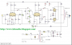
I found this schematic online that pretty much seems to match what I'm looking for (also in terms of Power transformer, but for an 5881 tube)
I recon I can replace the 5881 with EL34s. need to recalculate the biassing though.
I have enough information for now to continue I think.
Thanks to everyone who contributed already. Once I'm a bit further along after a simulation or so I might ask some more questions
and looking at the load line calculator of VTADIY: Vacuum Tube Amplifiers DIY - Vacuum Tube Amplifiers - DIY
it indeed seems that the 7k transformer is a bit low for the EL84 tubes
I can see it being suited for the EL34 or 5881 tubes.
I found this schematic online that pretty much seems to match what I'm looking for (also in terms of Power transformer, but for an 5881 tube)
I recon I can replace the 5881 with EL34s. need to recalculate the biassing though.
I have enough information for now to continue I think.
Thanks to everyone who contributed already. Once I'm a bit further along after a simulation or so I might ask some more questions
Attachments
Power transformer (Pri: 2x117V; Sec: 6.3V@3.1A, 6V@2.1A, 6.3V@2.2A and 260V@410mA with center-tab)(picture included)
OPT(7.2K Pri: center tab, no tabs for UL; Sec: tabs for 4, 8, 16 and 32 Ohm)
Tubes: 4 EL84 tubes and plenty of 12AU7, 12AX7 or 12AT7 to choose from
Ah-haa!
You have a workable set of irons...
The 260V outs can be put thru silicon bridge rectifier, then to PI network w/ coil separating big caps to give stout 360ish B+ with enough current to wake the dead.
Not sure about all those 6V outs... need some, but not all.
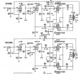
So for diagrams, I found this (attached)...
EL84 (6BQ5) PP w/ dual triode utility (7025)-- which I think you can sub your 12AX7's into... Not too complex for first endeavour, IMO.. and no UL taps required.
Jim
OPT(7.2K Pri: center tab, no tabs for UL; Sec: tabs for 4, 8, 16 and 32 Ohm)
Tubes: 4 EL84 tubes and plenty of 12AU7, 12AX7 or 12AT7 to choose from
Ah-haa!
You have a workable set of irons...
The 260V outs can be put thru silicon bridge rectifier, then to PI network w/ coil separating big caps to give stout 360ish B+ with enough current to wake the dead.
Not sure about all those 6V outs... need some, but not all.
So for diagrams, I found this (attached)...
EL84 (6BQ5) PP w/ dual triode utility (7025)-- which I think you can sub your 12AX7's into... Not too complex for first endeavour, IMO.. and no UL taps required.
Jim
Attachments
I found this schematic online that pretty much seems to match what I'm looking for (also in terms of Power transformer, but for an 5881 tube)
I recon I can replace the 5881 with EL34s. need to recalculate the biassing though. I have enough information for now to continue I think.
Thanks to everyone who contributed already. Once I'm a bit further along after a simulation or so I might ask some more questions
I think you may only need the last two stages of your schematic. The first stage may give you too much gain. Depends on the global feedback. You could also consider using the outputs in triode and dropping the negative feedback. Should give you a decent amount of power. I think you're on the right track here - 5881s will give you a variety of options for future mods. Plus if you make larger holes in the chassis you can fit 9 pin sockets in octal holes but not visa versa. Drivers too - 6SL7 is often used in place of ECC83.
If you're using a new chassis make sure it's big enough. You may want to move up to some nice parts that are bigger then the standard ones. Thinking of capacitors in particular.
Last edited:
Taking into account the comments of every one (to which I thank all of you)
and looking at the load line calculator of VTADIY: Vacuum Tube Amplifiers DIY - Vacuum Tube Amplifiers - DIY
it indeed seems that the 7k transformer is a bit low for the EL84 tubes
I can see it being suited for the EL34 or 5881 tubes.
I found this schematic online that pretty much seems to match what I'm looking for (also in terms of Power transformer, but for an 5881 tube)
I recon I can replace the 5881 with EL34s. need to recalculate the biassing though.
I have enough information for now to continue I think.
Thanks to everyone who contributed already. Once I'm a bit further along after a simulation or so I might ask some more questions
Because this is your first build I would not spend money on other tubes. You can happily use your transformers with EL84s. In the worst case you use triode connection (connect screen-grid g2 to the plate by means a 220R resistor, use 3W non flammable type) and 7K will be fine. I know that datasheets all suggest 10K for triode connection but the real difference won't be a problem. You can try to raise the anode current to 30 mA instead of the suggested 24 mA. If power should not reach 5W you might increase the plate voltage to about 320-330V. I know this is above max rating but if you use cathode bias it will be fine.
I run the PCL86 in my SE amp at 345V/24-25mA with a 7K transformer. It has been working fine for several years now......and I only use the cheapest types made in Poland or ex-Yugoslavia.
Last edited:
Sound advise, I would go for that setup.I found this (attached)... Not too complex for first endeavor.
Furst of all stop with that EL34 idea.It's not that the OPT is Raa=7k it is up to more power from bigger tubes.
Your schematic is for a guitar-amp, to sensitive input and that tone control
The oemcar one has missing stop resistors.
And both have a common cathode resistor
Every tube his own cathode resistor + decoupling capacitor !
Mona
Your schematic is for a guitar-amp, to sensitive input and that tone control
The oemcar one has missing stop resistors.
And both have a common cathode resistor
Every tube his own cathode resistor + decoupling capacitor !
Mona
Yes, about 7 kOhms isn't exactly what all EL84/6BQ5 datasheets call for the PP plate to plate impedance. But it isn't that far off. The difference even may take account for the ohmic losses in these OPT's. I guess (you didn't answer my specific question yet ) that all four EL84's and both OT's were in the same unit before? Which would mean that it works!
Go for the schematics shown some postings above, but replace (as Mona suggested) the common cathode resistor by individual resisotrs/capacitors for each tube. Or, even better, go for fixed biasing.
Designing a well working amp around what you already have isn't rocket science at all. Be courageous!
After all, repurposing given parts that came from old radios and televisions was the way most of us started their audio DIY hobby, me thinks. At least for me it was. And you really can call yourself a very lucky guy with these parts, believe me! I had to start with simple SE designs, as my first OPT that I butchered in the 1970ies was from an old TV with a PL84 final tube.
Good luck and best regards!
) that all four EL84's and both OT's were in the same unit before? Which would mean that it works!Go for the schematics shown some postings above, but replace (as Mona suggested) the common cathode resistor by individual resisotrs/capacitors for each tube. Or, even better, go for fixed biasing.
Designing a well working amp around what you already have isn't rocket science at all. Be courageous!
After all, repurposing given parts that came from old radios and televisions was the way most of us started their audio DIY hobby, me thinks. At least for me it was. And you really can call yourself a very lucky guy with these parts, believe me! I had to start with simple SE designs, as my first OPT that I butchered in the 1970ies was from an old TV with a PL84 final tube.
Good luck and best regards!
Gentleman, any specific output transformer must be calculated if one isn't using the exact working point from the datasheet. Thats the reason why in most cases its irrelevant what the manufacturer of the tube states in his standard datasheet for one given workpoint.
You have to calculate it for your amp anyway. So forget about any 7K transformer impedance discussion. Do calculate the exact needed impedance for a specific schemo and buy that output transformer. Or in reverse, change the schemo to fit for your already bought transformer. You can use nearly every schemo by changing its values.
You have to calculate it for your amp anyway. So forget about any 7K transformer impedance discussion. Do calculate the exact needed impedance for a specific schemo and buy that output transformer. Or in reverse, change the schemo to fit for your already bought transformer. You can use nearly every schemo by changing its values.
Last edited:
- Status
- This old topic is closed. If you want to reopen this topic, contact a moderator using the "Report Post" button.
- Home
- Amplifiers
- Tubes / Valves
- EL84 tube amp build, how to start?