OK, the sky is not the limit as far as funds go, but I have enough for a pair of Edcor push-pull OPTs.
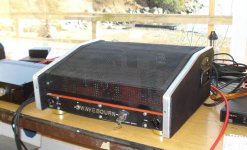
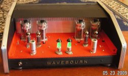
I have a small collection of GU-50 tubes and sockets, which I'd like to try. Yeah, they're beastly, but they look cool, I think.
I have a gigantic power transformer from an early 1970s Traynor bass amp, designed for 4x 7027A. It's massive. I can use that for the power supply for a gigantic stereo amp.
I don't need a lot of output power. 10 strong watts per channel would suffice. I would like good damping of the loudspeaker. So I'm thinking of going with a B+ of about 420V and cathode bias. Triode-wire the GU-50s, so they should see about 360V plate-cathode. That should be a good spot.
So, what plate-plate primary impedance should I go for? I'm thinking 10k ohms. The Edcor CXPP30-10K looks good.
Or would I be better off with the ever-popular CXPP25-7.6K ?
It looks like Zpri of anything from 7.5k to 10k should work well. See attachment.
The loudspeakers are Snell Acoustics E/III or Snell C (original version). Both are nominal 4 ohms, not 6 or 8.
Thoughts?
Attachments
")
Well, for push-pull class A triodes:
Higher value of Zprimary yields less power, lower distortion, better damping ratio.
Lower value of Zprimary yields more power, higher distortion, worse damping ratio.
Somewhere there is a 'most desirable' point for the particular designer's taste, intent.
I'm hoping to make the GU-50 triodes 'sound good' with a minimum of NFB. Maybe no global NFB loop if I can get away with it. That's why I was thinking of a high load impedance like 10k:VC.
My understanding about tying g3 to the plate along with g2 is that it doesn't make a huge difference from the usual configuration with g3 to cathode and g2 to plate. Or am I wrong about that?
I don't want to get into 'left-handed' vs. 'right-handed' vs 'CrazyDrive' and all that. Just plain triode wiring the old-fashioned way will be sufficient for my purposes.
--
Oh, NICE! That's exactly the kind of info that goes under the radar, but can make a big difference.
A 15% reduction in rp is pretty big.
I can give it drive. I'm thinking of using a Williamson-style driver circuit with a diff driver pair made of 6V6s in triode. I have a couple of PCBs for that, which I might as well use.
Thanks.
--
A 15% reduction in rp is pretty big.
I can give it drive. I'm thinking of using a Williamson-style driver circuit with a diff driver pair made of 6V6s in triode. I have a couple of PCBs for that, which I might as well use.
Thanks.
--
CXPP100-10K
It is what I used in my Pyramid amps 12 years ago.
850V B+, 270V regulated G2, +12V regulated G3.
100W max, driven by LTP on 6P15P with local parallel feedback from Gu-50 anodes.
It is what I used in my Pyramid amps 12 years ago.
850V B+, 270V regulated G2, +12V regulated G3.
100W max, driven by LTP on 6P15P with local parallel feedback from Gu-50 anodes.
Attachments
Last edited:
Thanks for reminding me. You got a ton of power out of those by running them at very high plate voltage (700V?), but much lower screen voltage (200V?). I remember well the 6P15P-triode drivers you used.
Do you think a 100W rated OPT is necessary if I'm going triode-wired with relatively low voltage B+/high plate current?
I'm thinking the operating points will be about Vp-k = 400V, Ip = 80mA, so grid bias will be in the neighborhood of -63V, each GU50 dissipating 32W.
I figure I should get about 15W per channel, no? That would be plenty for my small living room with big speakers. Maybe even with no global NFB loop. I will probably put one in, make it adjustable somehow.
Would a 30W capable output transformer not be enough? Go for the 50W one? I'm afraid of the big transformers having a lot of insertion loss and more leakage inductance, causing the higher frequencies to sound worse. I've never used one of these Edcor OPTs, so I don't know...
--
Attachments
I measured 840VCT unloaded, so I figure 800VCT under load.
I figure I can get about 450V DC out of it by using a couple of 5R4GA rectifiers in parallel to both withstand the current demand and drop the voltage. They'd probably drop about 40V.
The transformer came out of a huge Traynor bass amp 'head', but I don't remember the model number. I thought YBA-3, but I may be wrong.
The transformer's only identifying marker is the number "1969" on a sticker.
The laminations measure 11 cm x 9.5 cm x 9 cm, or 4.5" x 3.75" x 3.625"
--
Or maybe I should sell it! There's one on eBay with an asking price of $520 USD. That's amazing...
Last edited:
I believe the transformer is still being made by Hammond as a replacement for the original. It's their number 291YX.
https://www.hammfg.com/files/parts/pdf/291YX.pdf
The physical dimensions match perfectly. It's chunky. Weighs over 11 lbs.
Pretty hefty specs:
800VCT 534mA
6.3VCT 6A (I might use this winding for damper diode rectifiers)
120V primary
466VA
--
https://www.hammfg.com/files/parts/pdf/291YX.pdf
The physical dimensions match perfectly. It's chunky. Weighs over 11 lbs.
Pretty hefty specs:
800VCT 534mA
6.3VCT 6A (I might use this winding for damper diode rectifiers)
120V primary
466VA
--
Last edited:
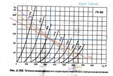
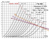
OK, so loadlines...
I'm no expert at this, but it looks like the triode mode plate curves I found published on the web have the screen grid and suppressor grid tied to the plate. Comparing this set of curves to the triode curves copied from the LS-50 data sheet, it certainly does look like the plate resistance is reduced and gm is increased (mu stays the same). I've attached that set of curves with my loadlines drawn on.
I drew the loadlines at Vp = 350V and Ip = 90mA (Pdiss = 31.5W).
It looks to me like a 3.3k loadline might be the best compromise between power and low distortion. That would mean I'd choose a 6.6k p-p Push-Pull OPT. Does that make sense?
It looks to me like the 4k loadline is flatter and will result in lower distortion, but not that much lower. Is it because the current stays more the same as the voltage swings that the higher load resistance results in less output power?
The 2.5k loadline looks usable, but definitely would result in more distortion. You can see how quickly the right side of the loadline dives down toward 0mA plate current.
So what looks better at that operating point? 4k? Or 3.3k?
(I think 3.3k, but I'm unsure...)
--
Attachments
Well... I've found that I like the sound of Class A push-pull triode amps. I had a push-pull 2A3 amp running with a 5k OPT that I thought sounded quite good, even though it's more common to see a 3.5k primary used for push-pull 2A3s. I only got 6 watts per channel out of it, though. I'm hoping to get a bit more out of this beastie. 12 watts would be nice.
In the curves graph in the previous post, at Vp = 350V and Ip = 90mA, it looks like rp is only 800 ohms.
Now, normally you'd say that 1600 ohms (2*rp) would be the load that would produce the most power output from the triode, so a 3.2k ohm push-pull OPT.
3*rp = 2400 ohms. so there's the 5k p-p OPT.
4*rp = 3200 ohms, so there's the 6.6k p-p OPT.
I don't know how to calculate damping on the speaker or Zout from the proposed amplifier, so I guess the best thing to do would be to err on the side of caution and go for the higher p-p primary impedance (i.e., 6.6k ohms rather than 5k ohms). But it looks to me like they'll all work.
Now where did I get the idea that I needed a 10k p-p primary? Maybe that would be if I wanted to run the tubes at the highest possible plate voltage and with cathode bias.
--
Last edited:
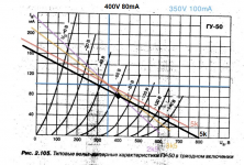
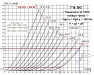
OK, here we go...
I took too small a sample along the -69.8V grid curve line in the plate curves. That's why I wound up with 800 ohms as the rp. But that is clearly wrong. It's too low.
I did it over, this time taking a much larger sample of the -69.8V grid curve, from Vp = 280V to Vp = 380V. The Ip changes from 16mA at Vp = 280V to 98mA at Vp = 380V.
98mA - 16mA = delta of 82mA.
delta of Vp / delta of Ip = 100V / 82mA = 1219.5 ohms.
Now the choices of OPT load make more sense.
A 5k push-pull OPT would present a load of roughly 2*rp to the GU-50-Triode.
A 6.6k p-p OPT would be 2.7*rp.
An 8k p-p OPT would be 3.28*rp.
A 10k p-p OPT would be 4.1*rp.
All would be reasonable choices.
5k would yield the most power, but least damping on the speaker.
10k would yield the least power, but most damping on the speaker.
The other two would be intermediate between 5k and 10k.
Decisions, decisions...
Attachments
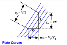
Wait...
What??
I thought I did what it shows here (attached graphic)...
--
And then there's this, from Triode Valve / Tube: Formula & Theory >> Electronics Notes:
Anode resistance
The anode resistance or plate resistance is more exactly described as the dynamic anode or plate resistance. It represents the resistance that the anode circuit offers to a small change in voltage.
Therefore when a small increment in anode voltage ΔEb produces a small change in anode current ΔIb the anode resistance can be calculated as follows:
Where:
rp = dynamic anode resistance
_____________________________
And so the question remains, is the rp of a GU-50-Triode 800 ohms, or is it 1200 ohms? There's a big difference...
--
What??
I thought I did what it shows here (attached graphic)...
--
And then there's this, from Triode Valve / Tube: Formula & Theory >> Electronics Notes:
Anode resistance
The anode resistance or plate resistance is more exactly described as the dynamic anode or plate resistance. It represents the resistance that the anode circuit offers to a small change in voltage.
Therefore when a small increment in anode voltage ΔEb produces a small change in anode current ΔIb the anode resistance can be calculated as follows:
rp = ΔEb/ΔIb = δEb/δIb
Where:
rp = dynamic anode resistance
_____________________________
And so the question remains, is the rp of a GU-50-Triode 800 ohms, or is it 1200 ohms? There's a big difference...
--
Attachments
Last edited:
- Status
- This old topic is closed. If you want to reopen this topic, contact a moderator using the "Report Post" button.
- Home
- Amplifiers
- Tubes / Valves
- Got some money, going to buy OPTs for PP GU-50