Why? Aren't we interested in the delta of the current and voltage of the actual device, and not some straightened tangent derived from measurements of the device?
I feel like I'm missing something big here.
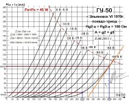
Figuring the rp from the orange line I get 0mA at 300V and 98mA at 380V.
380 - 300 = 80
0.098 - 0 = 0.098 = 816.33
Really??
I'd figure if you were going to draw a tangent, you'd draw it so that it intersects both points on your plate curve down to cutoff, so that you incorporate changes in plate resistance that happen as the tube approaches cutoff (where rp goes up and gm goes down). That's what I tried to accomplish with the thin red tangent I drew from the high voltage/high current point on the curve to the low voltage/low current point.
I'd better go look at the RDH4 again.
--
I feel like I'm missing something big here.
Figuring the rp from the orange line I get 0mA at 300V and 98mA at 380V.
380 - 300 = 80
0.098 - 0 = 0.098 = 816.33
Really??
I'd figure if you were going to draw a tangent, you'd draw it so that it intersects both points on your plate curve down to cutoff, so that you incorporate changes in plate resistance that happen as the tube approaches cutoff (where rp goes up and gm goes down). That's what I tried to accomplish with the thin red tangent I drew from the high voltage/high current point on the curve to the low voltage/low current point.
I'd better go look at the RDH4 again.
--
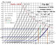
OK, I checked the books. It does seem you want to 'sample' the grid curve in a 'central' part of it, where the curve is fairly straight. That will tend to give you a lower value of rp.
rp = mu / gm , so if you know those two other constants you can figure out rp. Solving for mu first:
gm = δVp / δVg
- I found that starting from an operating point of Vp = 340V and Ip = 98mA, the grid bias is -60V.
- Grid bias is -70V at Vp = 380V
- Grid bias is -50V at Vp = 304V
δVp = 380-304 = 76V
δIp = 20V
76V / 20V = 3.8 <-- That's the mu
____________________________________
Now for gm
gm = δIp / δVg
- I found that at Vp = 320V and Ip = 120mA, Vg = -50V
- At Vp = 320V and Ip = 40mA, Vg = -70V
δIp = 80mA
δVg = 20V
0.08 / 20 = 0.004 <-- gm = 4mA/V
___________________________________
rp = mu / gm
3.8 / 0.004 = 950 ohms
___________________________________
In the latest scrawling on the plate curves, I drew a tangent from 320V-40mA (-70V) to 380V-98mA (-70V). That gives rp = 1035 ohms.
___________________________________
I'm going to split the difference and say rp = ca. 1000 ohms.
rp is not truly constant, so isn't a bit of a judgment call? Yes, at a particular operating point there is one value of plate resistance. But the plate resistance will vary once the triode starts swinging out of its linear window of operation.
So yeah, I think 1000 ohms works for me.
--
Attachments
")
Thank you TG!
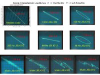
A few well-chosen 'scope grabs with real life loads speaks volumes. That's a spot-on illustration.
You got me to go back to the books on this. I'd read the chapters on calculating rp in the RDH4, MerlinB's and Morgan Jones' books, but I missed that crucial detail of how to choose a section of the grid curve to make the calculations. Yes, they talk about using the straight part of the curve. I see clearly now how that is just an approximation, an educated guess -- so there's no use nitpicking.
I learn better when I have a real life problem to solve, and this did the trick.
So, thanks again!
--
I've thought about a project like this for a while. I have a nice pair of 6.6k OPT's set aside and plenty of GU-50's but it seems too many other things have taken priority. Haven't decided what sort of driver circuit to use but probably either a fet follower like the Baby Huey project or interstage PP transformers. I think you could use 300b operating points as a good starting design since the triode curves are fairly similar. You might also consider a pentode design with local feedback. It can sound very triode like but with better power out.
Good luck and keep us posted,
John
Good luck and keep us posted,
John
Mostly I'm looking to start building things out of parts I've collected over the years. I have too much stuff!
I have a pair of OPTs from an Eico ST40. They're rated 8.2k pri:4,8,16 secondary, 20W, no screen taps so only pentode or triode operation feasible. The thing I worry about is if a 20 watt-rated OPT can take the 90mA quiescent plate current from each GU-50 triode. In theory the two tubes should be balanced, so the standing current nulls. But in practice? What happens when the amp gets driven into Class AB?
Perhaps I should leave those OPTs for a nice PP EL84 amp and purchase a pair of 50W rated OPTs for this project.
I calculate I'll get 13W per channel, Class A triode. Long ago, I built a PP 300B amp that made about that. It was pretty whompous, but it did hum some from its AC filaments.
The plan right now is to use a Williamson-style driver circuit employing 6SN7 voltage amp-6SN7 cathodyne to 6V6-triode LTP, then to the GU-50s. Open loop sensitivity looks like about 250mV to 1W out, approx. 1V to full power. That seems about right. I could add 6dB of gNFB if that ends up being desirable. Looks good on the screen, at least.
--
From the ST40 manual I can see that the tubes were originally biased at 56mA, and the OPT's primary DCR is just under 200 Ohm (each half).
So running GU-50 at 90 mA will add almost 2W of extra heat per OPT. Not optimal, but probably tolerable.
I wouldn't really be bothered about DC imbalance though, especially with self bias (and even more so with individual self bias).
So running GU-50 at 90 mA will add almost 2W of extra heat per OPT. Not optimal, but probably tolerable.
I wouldn't really be bothered about DC imbalance though, especially with self bias (and even more so with individual self bias).
Last edited:
Here's a post on this from years ago by Mike at Magnequest regarding his rule of thumb for calculating an acceptable bias current for an unknown transformer.
RE: Looking for a output trannie match, Scott LK72 - mqracing - Tube DIY Asylum
RE: Looking for a output trannie match, Scott LK72 - mqracing - Tube DIY Asylum
Here's a post on this from years ago by Mike at Magnequest regarding his rule of thumb for calculating an acceptable bias current for an unknown transformer.
RE: Looking for a output trannie match, Scott LK72 - mqracing - Tube DIY Asylum
calculate the voltage drop--- 90 ohms times 150 mils would be a voltage drop of 13.5 volts.
90 ohms times 75 mils would be a voltage drop of 6.75 volts
as a rule of thumb--- your probably not going to have a problem if you keep this voltage drop below 20 volts (in the context of an ot with tube friendly impedances and power supply voltages and etc). Remember it is a rule of thumb meaning someone, somewhere will be able to find a case where it would get you in trouble--- but they should be rare cases indeed.
generally---- my rule of thumb looks at anything less than a 20 volt drop as not being much to worry about--- again--- excluding the unusual or weird case that someone might dream up.
other rule of thumb is to calculate how many watts are dissapated across the winding----
90 ohms and 75 mils would dissapate about one half of one watt of power going up in heat. Not much at all.
formula is current squared times resistance
Hmmm...
So with Ip = 0.09A per winding, each winding (half of the primary) needs to have DCR of no more than about 220 ohms.
220R(0.09A) = 19.8V dropped across the winding
The power dissipated would be
0.09squared(220R) = 1.782 watts (hot!)
So it looks like 220 ohms per primary half would be marginal. Better to aim for 150 ohms or less.
Is this achievable? I don't know... I need to measure some OPTs.
--
A pair of 8k:VC OPTs meant for Push-Pull EL84 measure about 200R per primary winding, or almost 400R from plate to plate.
I guess those would be marginal for Ip = 90mA per tube.
--
Last edited:
Another push-pull OPT I have, with a 5k primary rated for 30W and 75mA per tube max, measures 85R per primary winding (170R plate to plate).
Specs for the Dynaco MK-III Output Transformer A-431:
4.3K Push-Pull with 33% Screen Taps to 4, 8, & 16 ohms 60 Watts
Frequency Response: 10 Hz to 100 kHz +/- 1 dB @ 1 Watt
Primary DC Resistance: 142 ohms
Primary Inductance: 40H @ 120 Hz
Hmmm, only 142 ohms. I think that's plate-to-plate too. So it does appear that a 50 or 60 watt OPT will work best for my application. The thing is, I remember what the Dyna A431 OPTs sounded like. I tried using them for a pair of 300Bs and 2A3s. They sound kind of big and dopey compared to something like the Dynaco A470 (ST70) or the OPTs from a Fisher 800C (why did I sell those off??). My suspicion is that big honkin' OPTs like the Dyna A431 have that big transformer thickness to their sound. Unfortunately, that's what's going to be required to run GU-50s safely with 90mA quiescent Ip. Am I right, or am I on the wrong track here?
Transcendar's 30W 6.6k OPT specs are:
6.6K Push-Pull to 4, 8, &16 ohms
Frequency Response: 10Hz to 100 kHz +/- 1 dB @ 1 Watt
Primary DC Resistance: 235 ohms
Primary Inductance: 65 H @ 120 Hz
Weight: 4 lbs
So 235 ohms plate-to-plate and 4 lbs each. Those are a lot lighter in weight than Edcor's 30W OPTs (6 lbs each). I wonder what that means...
It looks like if I want some headroom for high current swings, I may need a pair of big boy OPTs. Perhaps 50W rated.
--
Last edited:
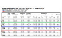
It seems Hammond Mfg gives max current ratings per each half of the primary for their push-pull OPTs.
I copied a table from their catalog, listing their PP OPTs.
Their part no. 1620 is rated 20W, 6.6k plate-plate primary, max Ip is 158mA per side. Weight is 3.5 lbs.
Part no. 1650H is rated 40W, 6.6k p-p primary, max Ip per side = 200mA. Weight is 6.5 lbs, which is similar to the Edcor CXPP45 and CXPP50 OPTs I was looking at (those are 6.75 lbs).
Part no. 1650P is rated 60W, 6.6k p-p primary max Ip per side = 200mA. Weight is 8 lbs, which is pretty darn heavy.
So... What does that tell us? I'm not sure. But it does appear that a 45W 6.6k primary OPT should work for a Class A amp running with each tube Ip = 90mA.
Hasn't anyone else puzzled this out before? Am I on the right track?
Attachments
Well, all three of those have pretty similar primary DC resistance which is quite low (70-80 Ohm per side), so any of them will work.
The bigger ones will give you better bass extension due to higher primary inductance and also less distortion in the LF region, but for me even the 1620 seems quite reasonable, so it is more of a size/weight/cost question.
The bigger ones will give you better bass extension due to higher primary inductance and also less distortion in the LF region, but for me even the 1620 seems quite reasonable, so it is more of a size/weight/cost question.
Rongon,
I have always interpreted the Hammond rating that is called “Max DC per Side” to mean the combined center tap current for two sides of PP, so I agree with your musings above.
You may also consider Toroidy - the Baby Huey guys have had very good results with them. The TTG-EL34 transformer seems to fit your requirements, and at ~US82 per piece delivered to the US very competitive.
TTG-EL34PP TOROIDY - Transformer: speaker | 50VA; O115x65mm; 0.008/54kHz; 200mA | TME - Electronic components
Note - shipping by TME is $9.90 per package under 5kg, so you have to buy and ship two individual TTG-EL34 transformers, since these weigh slightly over 2.5 kg each. I bought several Toroidy transformers from them and TME has delivered them to me in central USA within 5 bussiness day in every case. Unfortunately TTG-EL34 is currently out of stock; if interested you may want to contact TME customer service - they have been very responsive when I contacted them.
Interesting info there. Thanks.
I have a query in to Edcor about current ratings and primary DCR of some of their models. Waiting for the reply.
That TOROIDY OPT looks interesting alright. $82/each delivered is very competitive. My only concern is that toroids may require careful balancing of quiescent Ip of the output tubes. This makes things complicated. I suppose I could match the output tubes quiescent Ip. They are cheap enough. But they will drift with age, and I don't want to get into elaborate biasing schemes to keep the toroids from saturating on current imbalance. Have you found that to be an issue, and if so, how did you deal with that?
I was looking at the Edcor CXPP25-7.6K. There's no current rating or info on primary DCR, but it weighs 4.5 lbs (2 kg) each. What's interesting is that they can be ordered with a single 4 ohm secondary. This allows better high frequency response (reduced leakage inductance, interwinding capacitances). Since the speakers I'll be using are either 4 ohm rated or smaller ported bookshelf speakers, I'd rather work with a 4 ohm secondary than an 8 ohm. (They're also available with a single 6 ohm secondary.) The price for those would be about $160 for the pair, shipped.
If the 20-watt rated Hammond 1620 would work, perhaps the Edcor CXPP25 would also work.
Generally speaking, I look for clarity and smooth mids and highs rather than trying to get the deepest bass response. I might even put a HPF at the amp's input to restrict low end response, hoping that might reduce intermodulation distortion. My speakers don't go below 40Hz and I don't think the amps should try to go lower than that. Amplifier LF response of -3dB at 15Hz would probably be fine for my purposes.
The Hammond transformers are too expensive for what they are, but it was good to use them as examples for thought experiments.
--
rongon said:That TOROIDY OPT looks interesting alright. $82/each delivered is very competitive. My only concern is that toroids may require careful balancing of quiescent Ip of the output tubes. This makes things complicated.
Valid concern. But I have not seen any experiential complaints from any user about imbalance of currents/tubes using the Toroidy output transformers. They could have some small gab built-in. I better ask, because I have several unused pairs of those Toroidy’s.
- Status
- This old topic is closed. If you want to reopen this topic, contact a moderator using the "Report Post" button.
- Home
- Amplifiers
- Tubes / Valves
- Got some money, going to buy OPTs for PP GU-50