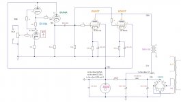
I tried to put together 4 tubes of which I have several unused pieces ... I don't know what came out of them... the doubts are mainly about the pins connection of ECC84 and 6AF4A, series resistor and cap on tube voltage regulator ...
Attachments
Last edited:
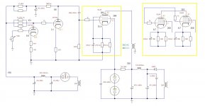
The 3K3 resistor won't last very long, as it's dissipating slightly more than 5W. A 20W part there would last indefinitely (not an aluminum house chassis mount one though!).
6W6s used as pentodes at the output will work well if this is a guitar amp. If it's for hifi use, you'll need to either use feedback or triode strap them to achieve suitable damping and distortion performance.
6W6s used as pentodes at the output will work well if this is a guitar amp. If it's for hifi use, you'll need to either use feedback or triode strap them to achieve suitable damping and distortion performance.
The 3K3 resistor won't last very long, as it's dissipating slightly more than 5W. A 20W part there would last indefinitely (not an aluminum house chassis mount one though!).
6W6s used as pentodes at the output will work well if this is a guitar amp. If it's for hifi use, you'll need to either use feedback or triode strap them to achieve suitable damping and distortion performance.
I have a lot of old big resistors... i understimate them, but they will be around 10w by side... i used it in another similar project and it resisted well (even if the scenario was not identical: 210v in - 3k 10w resistor - 150v voltage regulator - 140 mA approx.). In reality I can't understand which formula to use to get the right resistor ... so I would also know how to calculate the dissipated power.
I manually checked THD and actually saw that there is a lot and a lot of negative ... the situation with screen = 125v would be much better. Ultimately I used this setup to get all those 4 tubes in.
You don't need a cathode follower after an SRPP.
I wanted to lower the impedance by more than 2k.
You don't need a cathode follower after an SRPP.
Philips datasheet says: pin 7 should be connected to the imput circuit, pin 8 to the chassis.
You have about 230V of B+ on one side of the 3.3K resistor and 108V on the other. That's 122V across the resistor.
Power is (V^2)/R, so actually 4.5W
In my experience, a 5W resistor running at about 5W dissipation will last less than a year in daily use. A 5W resistor running at about 3W dissipation will last about two years in daily use, and a 5W resistor running at or below 1.6W will last forever.
For your 4.5W dissipation, I wouldn't use anything less than a 12W resistor.
I just checked 2 datasheets, a Mazda and a Philips, they both show pin 8 as a cathode connection. Maybe you should identify your reference in more detail?
I found it here: https://frank.pocnet.net/sheets/030/e/ECC84.pdf
I just checked 2 datasheets, a Mazda and a Philips, they both show pin 8 as a cathode connection. Maybe you should identify your reference in more detail?
You have about 230V of B+ on one side of the 3.3K resistor and 108V on the other. That's 122V across the resistor.
Power is (V^2)/R, so actually 4.5W
In my experience, a 5W resistor running at about 5W dissipation will last less than a year in daily use. A 5W resistor running at about 3W dissipation will last about two years in daily use, and a 5W resistor running at or below 1.6W will last forever.
For your 4.5W dissipation, I wouldn't use anything less than a 12W resistor.
I calculate a drop of 106v (214-108) and a current of 28 ca ... 3k3 should be able to moderate the current flow. but this was just my empirical evaluation ... however you can always use a trio of parallel 5w resistors...
I found it here: https://frank.pocnet.net/sheets/030/e/ECC84.pdf
You're right, it absolutely does say to ground pin 8 when using ECC84 as an RF cascode amplifier for a TV tuner.
I really don't know how I can communicate this more effectively. Do not ground pin 8. The datasheet is not telling you to ground pin 8 in your circuit.
6W6s used as pentodes at the output will work well if this is a guitar amp. If it's for hifi use, you'll need to either use feedback or triode strap them to achieve suitable damping and distortion performance.
Already there's not a substantial current feedback in the preamp section?
I don't know if you're asking me or audiowize, but typically gain is applied first so as to have a better sound to noise ratio by elevating a lower signal level earlier in the chain, and the second stage is about drive, so you would use a higher transconductance tube, which often have lower gain. Of course this a generalization and not absolute.
I don't know if you're asking me or audiowize, but typically gain is applied first so as to have a better sound to noise ratio by elevating a lower signal level earlier in the chain, and the second stage is about drive, so you would use a higher transconductance tube, which often have lower gain. Of course this a generalization and not absolute.
I asked anyone who wanted to answer me
") ... The intent is to design a preamp that has enough gain to drive most of the power tubes and at the same time has a fairly low output resistance without the aid of CF, buffers or other loopholes similar. I also thought that, logically speaking, it was better as you say, although I could get more or less the same resistance that came out in the reverse way ... but that easy solution could create other issues, i guess...
... The intent is to design a preamp that has enough gain to drive most of the power tubes and at the same time has a fairly low output resistance without the aid of CF, buffers or other loopholes similar. I also thought that, logically speaking, it was better as you say, although I could get more or less the same resistance that came out in the reverse way ... but that easy solution could create other issues, i guess...
Last edited:
I don't know if you're asking me or audiowize, but typically gain is applied first so as to have a better sound to noise ratio by elevating a lower signal level earlier in the chain, and the second stage is about drive, so you would use a higher transconductance tube, which often have lower gain. Of course this a generalization and not absolute.
Something similar to match most of the power tubes.
Attachments
Regarding PCC84: Yes, it has been designed as a Cascode amplifier for VHF TV frontends. The reason to bring out the bottom cathode on two pins was to separate both connecting wires' (input and output) inductances to avoid unneccessary negative voltage feedback. For audio use, I'd join both cathode pins.
Best regards!
Best regards!
- Status
- This old topic is closed. If you want to reopen this topic, contact a moderator using the "Report Post" button.
- Home
- Amplifiers
- Tubes / Valves
- 4 almost sleepy tubes