The whole schemo is strangely drawn. Resistors in series, resistors in parallel, and no dots where connections should be.
That's actually the MILSPEC way of drawing schematics. Wires that cross do not connect. Wires that meet at a T intersection are connected.
The resistors were probably connected in series to allow them to share the dissipated power. Maybe the original designer couldn't find 5 W types. Or maybe they wanted to use metal film resistors that were only available up to 2 W. Same for resistors in parallel. I think the only surprise is that the humdinger resistors on the 300B are actually four resistors in series/parallel. At least that's how I interpret it.
Tom
Last edited:
OK, never saw this MILSPEC kind of schematics.
If someone decides to put five resistors in parallel for enough power dissipation, that isn't recommended to draw in a schemo. For those documentary, an extra assembling plan has to be established.
In that, the wiring, parts locations and the whole structural building purpose can be described. So you can describe to use 20 pieces in parallel where the schemo just states one value. That makes sense.
What I say is good textbook practice and thats the way we learned and being told and everybody uses those principles except some folks who think they can do smarter. Even Mullard does it that way in their famous valve amps for DIY book.
Last edited:
drawing protocols
That you "never saw" does not mean it does not exist, nor is the way "you learned" the only correct option...
For example, check Broskie's site.
His drawings are without the dots you seem to need at every joint, but he draws dots where two lines cross and must have a connection.
Maybe you are confused with other protocols, maybe the simulation drawings where the dots are apparently needed to make the sim work?
Attachments
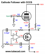
The schematic was originally designed to be part of a kit offered by hificollective. I assume parallel resistors are drawn separately to make it easy to keep track of part numbers. The designer also says this about the series resistors:
"I deliberately used two resistors in series to reduce the voltage across them. Too high a voltage across a resistor will cause it to become non linear with respect to the signal voltage. This phenomena is particularly pronounced with carbon resistors but it is present in all types."
"I deliberately used two resistors in series to reduce the voltage across them. Too high a voltage across a resistor will cause it to become non linear with respect to the signal voltage. This phenomena is particularly pronounced with carbon resistors but it is present in all types."
There isnt any problem with the schematic, just very opinionated views, you don't need to be a scientist to read a schematic.
Also your speakers or your ears dont care if you have a -3db response at 15hz you arent an elephant to reach that level of sensibility if it sounds good or not it wont be because of this, also the output transformer wont be happy with lower frequency response, it isnt a good practice either, it can lead to transient inestability.
Also your speakers or your ears dont care if you have a -3db response at 15hz you arent an elephant to reach that level of sensibility if it sounds good or not it wont be because of this, also the output transformer wont be happy with lower frequency response, it isnt a good practice either, it can lead to transient inestability.
And what does that exactly mean?Guitar amp with EF86? Jesus... too many stupid idiots on this planet, really!
You are gratuitously insulting a lot of people.
Everything: Too much noise, bad distortion signature, low current etc. The only advantage is high gain thats all. Despite that the EF86 has the tendency to sound sterile, brittle and gutless. My first preamp was build with EF86 but at that time I was young & inexperienced (Ablage: Jugend forscht).
Guitar amp with EF86? Jesus... too many stupid idiots on this planet, really!
Well not at all. VOX amplifiers have their place in music world and history! Guitar amps are NOT HiFi amps at any rate. It's as simple as that but clearly not so obvious.....
They follow different principle because they make music, they do not need to reproduce anything with fidelity.
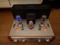
Last night I did my first serious listening and I had a big smile on my face To me it sounds awesome. Going to try the .22uf cap in place of the .015 because I already have one in my parts box, but it doesn't sound lightweight or bright at all. Bass is full and tight.
1 of the 300b's has that blue glow at the top of the tube, but I think it's fading already so I don't think it's an issue.
I have some e188cc's that I'll try in the 5687 positions and try some different EF86's I have laying around. But first impression is great, couldn't be happier
To me it sounds awesome. Going to try the .22uf cap in place of the .015 because I already have one in my parts box, but it doesn't sound lightweight or bright at all. Bass is full and tight.1 of the 300b's has that blue glow at the top of the tube, but I think it's fading already so I don't think it's an issue.
I have some e188cc's that I'll try in the 5687 positions and try some different EF86's I have laying around. But first impression is great, couldn't be happier
Attachments
Compared to what? For the gain you can get, the noise performance is great. They are certainly quieter than a 12AX7.Too much noise
Do you have any data on this? With 400V of B+ and a 100K plate load, an EF86 wired as a pentode will have a mu of ~140 and can put out 85V at 5% THD running a little over 3mA.bad distortion signature, low current etc.
A 12AX7 with that kind of plate voltage available will have roughly half the mu and half the voltage out at 5% THD.
It might be worth revisiting.Despite that the EF86 has the tendency to sound sterile, brittle and gutless. My first preamp was build with EF86 but at that time I was young & inexperienced.
Says the guy who build transistor guitar amps? LOL. Thats even worse than an EF86 LOL...
There's no reason to be rude to others.
Hi,
I have one thing I don't fully understand and that is the voltages on the EF86's. All readings in the amp match the schematic to a couple percent but the readings on the plates and screens of both ef86 tubes are off to as much as 20%.
I tried 2 pairs of tubes and they all read between 200v and 215v in the anode (pin 6) where the schematic says 175v. They screens (pin 1) should be 125 and I get between 109 and 117.
I'm not that worried about it but I would like to understand why this is and if I should address it (and why/how)
Thanks everybody
I am not an EF86 user.
With 400V B+, 200k plate load, 175V on the plate; that is only 1.1mA plate current.
That is what your schematic indicated. Your plate voltage is even higher, indicating less than 1.1mA
I would say that those resistive values were selected to get very large gain from that stage.
I would also say that the design is Starving the plate for current.
At that low of a current, different EF86 tubes will quite possibly have a very large spread of plate voltage.
I think you are observing that you are getting exactly what the design dictates.
I have seen other designs using EF86. Some have very repeatable voltage results from tube to tube.
Others, which put the EF86 at the extreme of low current; (or at the extreme of low plate voltage, not your case) will get wildly different results.
I will admit, I have often wanted to use an EF86 as the input tube of a 2 stage amplifier, but the high price of the tube overcomes my curiosity.
Someday . . . perhaps.
Just my opinion.
If it sounds good, I bet everything is OK, even with the different voltages. Do not worry, it will not burn out.
Happy listening!
Last edited:
You might try changing the EF86 cathode resistor from 2.2k to . . .
Either 2.0k
Or 1.8k
Then reduce the Screen resistor from 1Meg in series with 470k, to . . .
Either 1Meg in series with 330k
Or 1 Meg in series with 270k.
That might make the voltages closer to the schematic,
But it might or might not change how it sounds.
Either 2.0k
Or 1.8k
Then reduce the Screen resistor from 1Meg in series with 470k, to . . .
Either 1Meg in series with 330k
Or 1 Meg in series with 270k.
That might make the voltages closer to the schematic,
But it might or might not change how it sounds.
Guitar amp with EF86? Jesus... too many stupid idiots on this planet, really!
I own a Vox AC10 JMI imported from England in 1965 during the peak of the Beatle craze. Its a 2x10 portable. I bought it for $25 in 1973 at a garage sale. It uses EF86, its still using the original Mullard, but I can't say that its ever sounded thin, just the opposite. I can get a pretty fat yet clean tone. Its nice to have a higher gain channel with the EF86 ahead of the tone stack and tremolo losses. The low channel uses a different input tube, but I don't have the schematic in front of me right now.
- Status
- This old topic is closed. If you want to reopen this topic, contact a moderator using the "Report Post" button.
- Home
- Amplifiers
- Tubes / Valves
- Help debug 300B amp, thin sound, low volume