Greetings to all,
I have developed a board for a heater supply that is capable of 1.5A and can be upgraded to higher currents by substituting a different part for the LM337
Its a mix of known circuits, and works pretty well in testing, there are currently half a dozen of these modules operating, and the first feedback is positive. With some raving reviews from some friends that have tried these in their amplifiers.
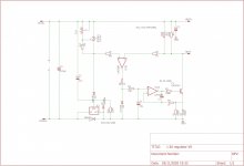
See the attached circuit diagram, its essentially a TL431 reference, biased by a LM337 in the negative lead, followed by a current source that is voltage driven by a comparator through a low pass filter.
The diode D4 increases the voltage over the current source by another 650mV or so, so the 2SC6144 transistor is in its linear operating region.
Diode D3 serves to keep the current ramp up characteristics of the current source independent of supply voltage, this means the circuit will have a nice soft start characteristic whereby the current is brought up slowly, keeping thermal shock of the filaments to a minimum. Furthermore it also provides a limit to the amount of current that a cold filament can draw during start-up.
R1 and R2 are the current sense resistors, with a 1n4148 for D3 the maximum drive to the opamp-transistor current source is about 650-700mV depending on exact supply voltage and diode production lot. This will yield a short circuit current of ~2A for the current source with the values as per the schematic.
Current source frequency compensation
R4 C1 serve to make the circuit more stable with light inductive loads, i have not optimized the value of C1 very much because the circuit seems stable with leads in of several meters.
Upgrade to 2.5A
By replacing R1 and R2 with 390mOhm 2W metal oxide resistors and replacing the LM337 with the 3A LT1033 allows for 2.5A of current.
Circuit advantages,
One of the advantages of the LM337 pre-regulator setup is that the voltage over the 2SC6144 transistor is tightly controlled by the circuit which increases reliability, and furthermore the input voltage is not too critical because the LM337/LT1033 both have internal over-temperature protections.
The diode clamping on the output of the comparator yields very nice startup behaviour on most directly heated tubes.
Noise is also very low, i cannot measure it very well with the limited test equipment i have available for the job, but most meters agree its somewhat lower than 100uV. With some popcorn noise visible on my Rigol oscilloscope.
Disadvantages
This circuit is not exactly efficient, by deleting the pre-regulator and lowering the value of the sense resistors, dropout could be lowered to half a volt. enabling the supply to run from AC to DC in most 5V and up DHT's
try the circuit yourself,
I have lots of boards available, and can also provide kits with all the components needed to build this circuit yourself.
There is a group buy for these regulators here: Group buy filament regulator for DHT tubes
I have developed a board for a heater supply that is capable of 1.5A and can be upgraded to higher currents by substituting a different part for the LM337
Its a mix of known circuits, and works pretty well in testing, there are currently half a dozen of these modules operating, and the first feedback is positive. With some raving reviews from some friends that have tried these in their amplifiers.
See the attached circuit diagram, its essentially a TL431 reference, biased by a LM337 in the negative lead, followed by a current source that is voltage driven by a comparator through a low pass filter.
The diode D4 increases the voltage over the current source by another 650mV or so, so the 2SC6144 transistor is in its linear operating region.
Diode D3 serves to keep the current ramp up characteristics of the current source independent of supply voltage, this means the circuit will have a nice soft start characteristic whereby the current is brought up slowly, keeping thermal shock of the filaments to a minimum. Furthermore it also provides a limit to the amount of current that a cold filament can draw during start-up.
R1 and R2 are the current sense resistors, with a 1n4148 for D3 the maximum drive to the opamp-transistor current source is about 650-700mV depending on exact supply voltage and diode production lot. This will yield a short circuit current of ~2A for the current source with the values as per the schematic.
Current source frequency compensation
R4 C1 serve to make the circuit more stable with light inductive loads, i have not optimized the value of C1 very much because the circuit seems stable with leads in of several meters.
Upgrade to 2.5A
By replacing R1 and R2 with 390mOhm 2W metal oxide resistors and replacing the LM337 with the 3A LT1033 allows for 2.5A of current.
Circuit advantages,
One of the advantages of the LM337 pre-regulator setup is that the voltage over the 2SC6144 transistor is tightly controlled by the circuit which increases reliability, and furthermore the input voltage is not too critical because the LM337/LT1033 both have internal over-temperature protections.
The diode clamping on the output of the comparator yields very nice startup behaviour on most directly heated tubes.
Noise is also very low, i cannot measure it very well with the limited test equipment i have available for the job, but most meters agree its somewhat lower than 100uV. With some popcorn noise visible on my Rigol oscilloscope.
Disadvantages
This circuit is not exactly efficient, by deleting the pre-regulator and lowering the value of the sense resistors, dropout could be lowered to half a volt. enabling the supply to run from AC to DC in most 5V and up DHT's
try the circuit yourself,
I have lots of boards available, and can also provide kits with all the components needed to build this circuit yourself.
There is a group buy for these regulators here: Group buy filament regulator for DHT tubes
Attachments
-
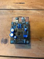 photo_2020-10-27_10-19-03.jpg168.8 KB · Views: 896
 -
 photo_2020-10-27_10-19-21.jpg154.1 KB · Views: 889
 -
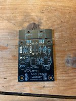 photo_2020-10-27_10-19-25.jpg243.8 KB · Views: 1,003
 -
 Schema prereg regulator.jpg397 KB · Views: 1,054
 -
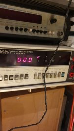 photo_2020-11-14_17-59-27.jpg66.8 KB · Views: 1,026
 -
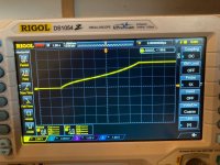 photo_2020-10-19_15-53-07 (2).jpg166 KB · Views: 317

Combining cheapo 3-terminal regulators and opamps has been tried before. Even the celebrated Thorsten Loesch - a very capable all-round designer - tried it a few years ago, but the results were neither good-sounding, nor quiet.
Thorsten's was sold by DIY HiFisupply, in HK, and used in the DIYHFS amp kits, such as the TRAM II.
I lost count of happy conversions from these modules to my filament regulator, and as an example, here's one in the open forum space:
TRAM-II-Filament Regulator upgrading
I would happily avoid posting or even seeing spammy threads of this kind (which are against the forum RULES), but they seem to have become normalised, the OP most persistent recently; my apologies for adding to it.
So just because some other person who presumably has a engineering degree and lots of fame in the DIY community couldn't get something to work this circuit is automatically garbage?
Then you invoke the forum rules, which you also broke by threadjacking Guido tent's topic on the same matter. New DHT heater
Instead i post something with the schematic so others can improve upon it, or give valid criticism in the spirit of DIY.
Everytime i post something on the matter, you come in and bite my head off. I would get defensive too when i'm selling something at a 400-900% margin.
Ive had it with this boomer enclave and its entrenched interests.
As far as I know v4lve lover doesn’t intent to become rich from his online sales. He has offered us on diyaudio a lot of interesting board designs with free Gerbers. These are very much appreciated by the diy community. I haven’t used anything yet, nor bought anything, but I do appreciate v4lve lover’s proactive attitute towards the diy community.
Let everyone make his/her own decision what to buy, to build, etc..
Regards, Gerrit
Let everyone make his/her own decision what to buy, to build, etc..
Regards, Gerrit
Such a lot of drama.
> So just because some other person who presumably has a engineering degree...
The limitations of the parts are enough.
> threadjacking Guido tent's topic
I spent six years on that thread, and other threads, encouraging folks to make their own regulators. My productionised design did not appear until August 2010, after so many requests to make something available.
> Everytime i post something on the matter, you come in and bite my head off.
That is flat-out false. The only attack you had from me was in response to a bogus assertion that my power transistors were not rated for reliability.
If you don't think so - kindly show the posts.
> boomer enclave
Nobody is going to apologise for their age.
you are right heat of the moment. im quite proud of this little circuit and your post rubbed me the wrong way, mea culpa.
I have stress tested the 6144 on multiple occasions now, and they seem to fail instantly only around 22-24W on a 2K/W heatsink . You where vindicated in your assertion that they are within specifications. I personally would have built in more margin but that is a matter of taste not engineering prowess.
One neat little thing about this circuit i think is that it behaves like a voltage source for low frequencies and as a current source at high, what this will do to THD i dont know. All that i know is that what i am able to measure with my limited test setup. which is limited to say the least.
You can increase the value of the RC filter, to lower the transition from low impedance voltage source to higher impedance current source but you risk overshoot during warmup this way with some thoriated filament tubes.
Last edited:
I can see nothing wrong with new designs. I'm sticking with Rod's regs - they've comfortably out-performed anything else I've heard.
I'd also point out that Rod is a person of total integrity in my several years knowledge of the guy.
But by all means carry on inventing - it's what we do.
I'd also point out that Rod is a person of total integrity in my several years knowledge of the guy.
But by all means carry on inventing - it's what we do.
Would it not result in IM distortion, riding along the fil-anode capacitance into B+?I always wanted to try a high frequency AC source, say a 1Mhz sinewave. Someone in Glass Audio tried an RF powered filament supply but it was tube based and more complicated than the amplifier.
Yes, ultrasonic or even higher frequencies will cause IMD in the output if ANY sources of signals and noise are mixed (in the multiplier sense) with the heating carrier. This means that sum and difference products (and their multiples) will appear. Some of these will be in the audio band.
The notion of ultrasonic/RF heating arose at the end of the 1990s, when constructors found that ac-heat did not sound so bad as DC heat using passive solutions (that do not contain or protect the filament's music signal) - or even worse, voltage regulators, which try to cancel the music signal as an "error".
When the solutions for well-implemented DC heating arrived shortly after that, the space for fringe solutions of that kind disappeared.
At best, it might sound better than AC-heat - but that's not saying much.
Last edited:
... I have stress tested the 6144 on multiple occasions now, and they seem to fail instantly only around 22-24W on a 2K/W heatsink ...
Saying that the transistors failed at lower power without specifying the transistor's case-temperature [Tc] is meaningless.
If your C6144s fail below 25W, it is because you did not restrict the case temperature to 25 °C or less, or you missed the restriction on pulse-width - or else you did not respect the other major data-sheet condition: the Safe-Operating-Area, especially the second-breakdown region. For example at Vce=10V at Ic=2A, second breakdown reduces the maximum power to 20W.
Thermal design is not a matter of personal taste. It is an understanding of the performance of devices under ALL of the operating conditions they face in real life, and the relationship between temperatures and long-term reliability.
... But by all means carry on inventing - it's what we do.
Yes, that's right - and I don't wish to stand in the way of offering ideas.
My peeve with Florick (the OP), apart from clumsy attacks on my designs - is that he is abusing the forum to try to gain advantage.
For example Group Buys are on the forums here to allow members to get together to obtain a high-quantity price from a supplier. So - the forum is provided for the advantage of our Members.
But in this case, the OP tells us that he has Lots of Boards available already, and parts. It's not a Group Buy, for the advantage of the Members, but a promotion dressed up as a Group Buy - for the advantage of the seller.
I always wanted to try a high frequency AC source, say a 1Mhz sinewave. Someone in Glass Audio tried an RF powered filament supply but it was tube based and more complicated than the amplifier.
At this frequency and this power the source will be a nice radio transmitter that will perturb many radio devices in the neighborhood. Must be shielded and is not no easy.
Yes, that's right - and I don't wish to stand in the way of offering ideas.
My peeve with Florick (the OP), apart from clumsy attacks on my designs - is that he is abusing the forum to try to gain advantage.
For example Group Buys are on the forums here to allow members to get together to obtain a high-quantity price from a supplier. So - the forum is provided for the advantage of our Members.
But in this case, the OP tells us that he has Lots of Boards available already, and parts. It's not a Group Buy, for the advantage of the Members, but a promotion dressed up as a Group Buy - for the advantage of the seller.
The difference i wanted to highlight at the time is that you used 25W parts whereas i was using a 340odd watt linear mosfet to do the same thing.
Those 2SC6144 actually surprised me at their ability to withstand the dissipation, and you where right. But instead of reiterating that it was entirely within specifications. You gave me a whole paragraph to chew on. Where you put away something i made as untested trash.
You are right again, if i can il have the group buy thread moved, or reduce the price. the parts and PCB's are about 7.50 eur from the top of my head. il reduce the price to 10 for the kits. so it is more in line whit what a group buy should entail.
I made the group buy thread when i already had some major inventory of the parts, but held off on ordering ROHS-ENIG boards before solid interest.
Abusing the forum, well that is kind of harsh, one the one hand yes i sometimes offer stuff at above purchase price and promote my designs. But on the other i don't mind posting the design files for something so people can order and build something themselves. I try to give valid design advice to newcomers, and have offered up much of what i have drawn in therms of PCB's for free.
In all i say my behaviour has been a mixed bag, and i'm asking you not to like me but to tolerate me as a person. I know i have my quirks but lashing out only serves to annoy both of us.
What is to be proven needs to be proven.
I have a set of built regulators on heat sinks available for free to anyone in the EU that has the measurement equipment to do noise measurements on them and post the results here. Shipping is on me as well.
Outside the EU is also possible, but you pay for postage.
I have a set of built regulators on heat sinks available for free to anyone in the EU that has the measurement equipment to do noise measurements on them and post the results here. Shipping is on me as well.
Outside the EU is also possible, but you pay for postage.
Last edited:
D1 on the PCB silkscreen is reversed.
Hi v4lve lover,
Just stumbled across this thread and I am highly interested in your tube filament regulator design. Is there a possibility to supply a PCB board design picture so I can use that for my own PCB software program Fritzing. Fritzing does not have the possibility to show a Gerber view and then translate it into a PCB.
Now i am curious as to what exactly you want to change, and what you want to do with the design? If its for commercial use its different from hobby projects.
Gerbers are posted on this page, feel free to order those from JLC anytime you please. If you need specific parts let me know, i have everything.
Gerbers are posted on this page, feel free to order those from JLC anytime you please. If you need specific parts let me know, i have everything.
Now i am curious as to what exactly you want to change, and what you want to do with the design? If its for commercial use its different from hobby projects.
Gerbers are posted on this page, feel free to order those from JLC anytime you please. If you need specific parts let me know, i have everything.
No, it is absolutely not for commercial use. I am intending to use it for my ECC99 or ECC88 input stages.
And because I did not see any address where I can order your design I decided to make a PCB myself using my PCB program Fritzing.
- Home
- Amplifiers
- Tubes / Valves
- DHT heater supply design